Lutron Dimmer Switch Wiring Diagram (Easy 1-Pole & 3-Way)
Lutron makes dimmers for different lighting loads and circuit arrangements. A single-pole dimmer controls a light from one location; a 3-way arrangement controls the same light from two locations. The correct wiring diagram depends on the exact dimmer model and the existing circuit, so a generic diagram cannot safely cover every Lutron product.
This guide explains what to check before choosing a Lutron dimmer and where to find its model-specific wiring diagram. It does not provide instructions for opening a switch box, testing live conductors, or connecting wires. Have a licensed electrician assess the circuit if the manufacturer’s instructions do not clearly match it.
Key Product Checks
Before selecting a device, check the full model number and the product documentation. Lutron models do not all use the same leads, terminals, neutral requirements, load ratings, or companion controls.
- Circuit type: Confirm whether the model supports single-pole, 3-way, or another listed control arrangement.
- Lighting load: Check the exact bulb or fixture type and its compatibility with the dimmer. LED compatibility can vary by model and lamp.
- Device rating: Use the dimmer’s marked ratings and current installation guide. Do not apply wattage examples from a different model.
- Box and wiring: Box capacity, conductor condition, grounding, and any required neutral must be assessed against the instructions and local requirements. Ask an electrician if these details are unknown.
Technical Tools & Materials Required
Electrical test instruments and wiring tools are for a qualified person working under the device instructions and safe work practices. A non-contact voltage detector is only a preliminary indicator; it does not prove that a circuit is safe to touch. This guide does not instruct readers to test or alter household wiring. Before an electrician visits, you can gather the dimmer and lamp model numbers, packaging, and any error or compatibility information without removing a switch or cover.
Lutron Dimmers and Lighting Compatibility
Different dimmers use different control technologies and support different types of lamps and transformers. Terms such as forward-phase (leading-edge) and reverse-phase (trailing-edge) describe broad dimming methods; they do not, by themselves, tell you which Lutron model is suitable for a particular LED, transformer, or fixture.
Check the compatibility list for the exact dimmer and the exact bulb or fixture model. If the lighting is integrated LED, use the fixture model rather than assuming a replacement-bulb chart applies. Do not infer a dimmer’s compatibility from its appearance or from a general statement about leading-edge or trailing-edge control. The manufacturer’s documentation should specify the supported loads and any relevant setup or companion controls.
Single-Pole Lutron Dimmer Switch Wiring
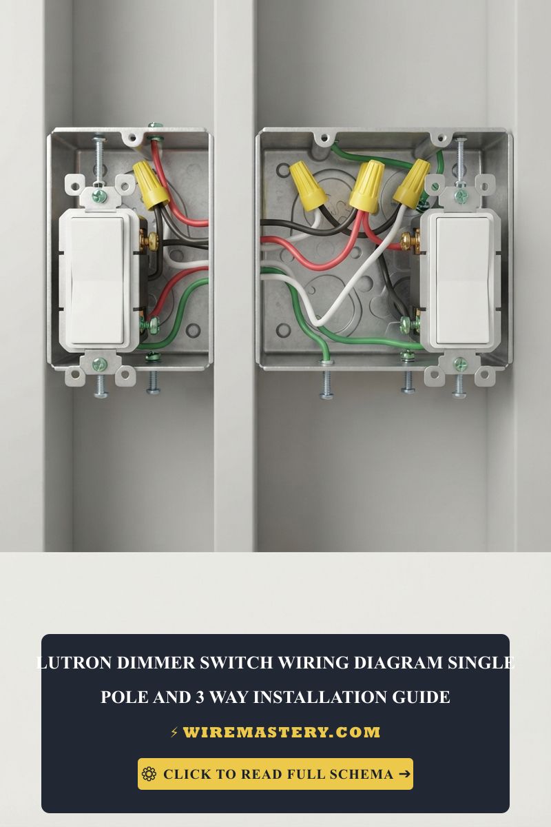
A single-pole Lutron dimmer controls a light from one wall location. The model’s diagram may identify terminals or leads for line, load, neutral, and equipment ground, but not every dimmer has the same set or color of leads. House-wire color alone does not confirm a conductor’s function.
Single-Pole Diagram: What to Confirm
Use the wiring diagram supplied for the exact model and verify that it is labeled for a single-pole installation. Check the model number, supported lamp type, load rating, neutral requirement, and any instructions for a second switch or accessory. Do not transfer a black/ red/green lead assignment from another Lutron model. If the diagram and the existing circuit do not clearly match, stop and have an electrician identify the circuit and complete the installation.
Three-Way Lutron Dimmer Switch Wiring
A 3-way circuit lets two wall controls operate one lighting load, such as at both ends of a hallway or at the top and bottom of a staircase. The Lutron dimmer may be designed to work with a standard mechanical 3-way switch or with a specific companion control. Which arrangement is supported depends on the exact model.
Deciphering Traveler Lines in 3-Way Loops
On a conventional mechanical 3-way switch, the common terminal is often identified by a darker screw, while the traveler terminals are often a pair of brass screws. Those conventions describe device terminals, not the function of unidentified house wires. In a Lutron installation, lead colors, terminal labels, and the permitted companion arrangement depend on the product.
Use the diagram for the exact Lutron model and the correct 3-way arrangement. It should match whether the product is used with a mechanical switch or a listed companion, and whether dimming is available at one or both locations. Do not energize an open switch box or guess the common or traveler wires from insulation color. Ask an electrician to verify the circuit if its layout is uncertain.
If the light also needs to be controlled from additional locations, see our overview of 4-way light-switch diagrams and switching arrangements. A 4-way circuit is a different arrangement; do not apply its diagram to a 3-way Lutron dimmer.
Multi-Gang Boxes and Dimmer Ratings
Some dimmers have side sections or tabs that affect heat dissipation when devices are installed next to one another. Do not break off tabs or apply a generic wattage reduction. The permitted configuration and resulting load rating are model-specific and must come from the current Lutron instructions for that device. Box fill is a separate installation requirement; an electrician can verify both the box and the dimmer’s ratings for the actual installation.
Before Installation
- Record the full Lutron dimmer model and the bulb or fixture model; do not rely on the product family name alone.
- Find the current installation guide from Lutron and confirm it covers the single-pole or 3-way arrangement you intend to use.
- Check the required companion control, lamp compatibility, load rating, neutral requirement, and any model-specific multi-gang instructions.
- If the guide does not clearly match the existing wiring, leave the switch in place and ask a licensed electrician to assess and install the device.
This article does not give wire-splicing instructions. Lead types, approved connectors, strip lengths, and terminal torque requirements vary by product and must follow the exact manufacturer’s instructions.
Troubleshooting Common Lutron Dimmer Issues
- The 3-way controls do not behave as expected: The selected dimmer may require a specific mechanical switch or companion control, or the installation may not match the model’s diagram. Do not remove the controls or probe conductors to diagnose it; check the model documentation and contact an electrician.
- LEDs flicker, buzz, or have a limited dimming range: Confirm the exact bulb or fixture appears on the dimmer’s compatibility list and check the model’s troubleshooting guidance. These symptoms alone do not prove a wiring fault.
- The breaker trips, a control becomes unusually hot, or there is a burning smell: Stop using the circuit and contact a qualified electrician. Do not repeatedly reset a tripping breaker or open the switch box to investigate.
Lutron Instructions and Local Code
Grounding, box capacity, device listing, and installation requirements depend on the product and the electrical rules adopted in your location. Do not assume that every Lutron dimmer has the same grounding or neutral requirements. Follow the exact product instructions and local requirements; a qualified electrician can assess the existing installation.
Frequently Asked Questions About Dimmer Switches
Is a flickering light a hazard when using a dimmer switch?
Not always. It can result from lamp incompatibility or a dimmer setting, but it can also indicate an electrical problem. Check the exact lamp and dimmer compatibility information without opening the switch box. Stop using the control and contact an electrician if there is unusual heat, buzzing, a burning smell, or a breaker that trips. For broader warning signs, see our guide to flickering lights and possible electrical hazards.
Where can I find a Lutron dimmer wiring diagram?
Use the installation guide for the exact Lutron model and circuit type. A diagram for a different model or a generic LED dimmer may show different terminals, leads, or companion controls. Lutron’s support site lets you search for product-specific guidance.
Can the same Lutron diagram be used for single-pole and 3-way wiring?
No. Single-pole and 3-way are different circuit arrangements, and Lutron models have different wiring diagrams and supported companion controls. Confirm the exact model and circuit type in the manufacturer’s instructions; do not adapt one diagram to the other.
Official Product and Safety Information
For product-specific Lutron diagrams, compatibility information, and troubleshooting, start with the official Lutron support site and search by the dimmer’s full model number. Electrical code and permit requirements vary by location; consult a qualified local electrician rather than relying on a generic online code summary.
Conclusion
The right Lutron dimmer switch wiring diagram depends on whether the circuit is single-pole or 3-way, the exact dimmer model, and the connected lighting load. Use the manufacturer’s diagram for that model and have an electrician assess any wiring that is unclear. This keeps the page focused on both single-pole and 3-way Lutron dimmers without treating one product’s connections as universal.