Top Smart Home Automation Devices: Contractor Installation Guide
Engineering a resilient, residential microgrid or deploying an ecosystem of high-performance smart home automation devices across modern property footprints demands a disciplined operational mastery of digital signaling physics, harmonic shielding protocols, and strict overvoltage category boundaries. Within contemporary building construction frameworks, transitioning a legacy property into an automated smart home can no longer rely on unshielded retail hardware plug-ins or fragmented wireless networks. As high-density data processing loops, automated climate sensors, and solid-state security nodes integrate into the primary 120V/240V AC power grid, executing the hardware wiring poorly introduces dangerous electromagnetic interference (EMI) and destructive transient line surges. Bypassing core isolation guidelines will instantly fry logic processor boards and distort sensitive data logging streams behind finished wall channels.
To protect sensitive automated frameworks from progressive line insulation decay and maintain absolute code-compliant link equity across structural footprints, project developers must anchor these installation steps straight to verified commercial electrical blueprint schedule layouts and follow our dedicated technical parameters for wiring no-neutral smart switches using capacitance bypass modules.
This smart home devices procurement reference manual despatches the fundamental processes required to map centralized automation topologies, calculate low-voltage signal drop constraints, and employ advanced on-site diagnostic laboratory toolkits.
Core Home Automation System Parameters
Before layout planning or pinning low-voltage microcontroller interfaces into operational relays, decode these foundational boundaries. Apply those low-voltage separation rules to the smart-home installations discussed here.
- The Power Siphoning Leakage Floor (NEC 404.2(C)): To bypass the absence of an explicit neutral return line inside legacy switch cavities, certain no-neutral automated devices bleed a tiny standby current down the equipment grounding conductor rail. The National Electrical Code strictly caps this ground-bleeding leakage at a maximum ceiling of 0.5 milliamperes (mA) to prevent fatal shock tracks across exposed metallic faceplates.
- The Inductive Kickback Vector: When power is cut to an electromechanical relay or heavy contactor coil driving an automated pool pump or HVAC blower fan, the internal magnetic field collapses instantly. This rapid collapse induces a massive, inverse high-voltage transient spike—known as counter-electromotive force or back-EMF—that shoots backward down the signal line, exceeding hundreds of Volts. Bypassing an integrated flyback clamping diode will instantly punch holes through switching transistors.
- The Ready Accessibility Mandate (NEC 408.18): All centralized smart home automation server racks, power distribution subpanels, and low-voltage transformer cabinets must be readily accessible and situated where maintenance personnel maintain a clear workspace envelope of 3 feet of front depth clearance under NEC 110.26 rules, fully blocking the storage of household boxes or cargo adjacent to component frames.
Technical Materials & High-Frequency Automation Diagnostic Toolkit Reference
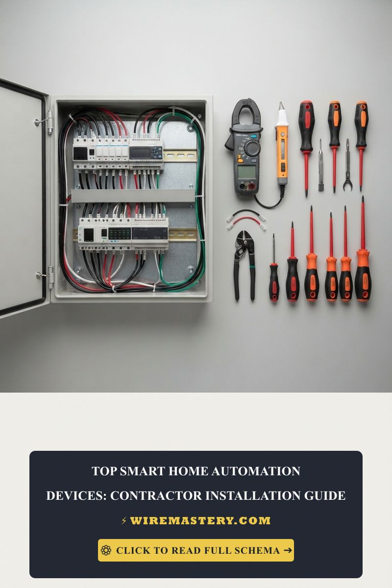
Safely opening energized low-voltage signal gutters and tracking high-frequency network attenuation fields requires specific category-certified laboratory testing instrumentation:
| Smart Home Auditing Tool | Primary Engineering Purpose & Trade Safety Threshold |
|---|---|
| Fluke DSX-8000 Certifier | Certified field certifier used to audit Cat6A line compliance up to 2 GHz frequencies. |
| True RMS CAT III Multimeter | Category CAT III 600V certified to accurately check branch voltage sags and path resistances. |
| Non-Contact AC Proximity Wand | Proximity sensor calibrated to audibly guarantee 100% box de-energization before wire handling. |
| 1000V Insulated Square Driver | Square-tip (Robertson) insulated tips to prevent lateral slips against live tabs. |
| Class 00 Dielectric Rubber Gloves | Certified high-density rubber wraps rated to block up to 500V AC continuous contact tracks. |
Conductor Profiles & Data Bandwidth Loading Metrics (ANSI/TIA-568)
When mapping out material specifications for an automated smart home infrastructure network, standard electrical wiring diameters are replaced by specialized communications dimensions.
- 23 AWG Solid Copper Category 6A Line: The modern gold standard for high-bandwidth home networks. It features thicker solid copper conductors and tighter internal pair twists than older Cat6 variants, eliminating signal attenuation across extensive path runs.
- 14 AWG Solid Copper Conductor (15-Amp Circuit Limit): Standard white sheathing profile. Deployed across standard residential lighting tracks and general bedroom convenience branches supplying power to smart hubs.
- 12 AWG Solid Copper Conductor (20-Amp Circuit Limit): Heavy-duty yellow sheathing profile. Mandatory across high-density residential automation layouts, kitchen islands, and master bathrooms to handle heavy continuous currents safely.
Technical Phase 2: Centralized Smart Hub Wiring & Signal Noise Mitigation
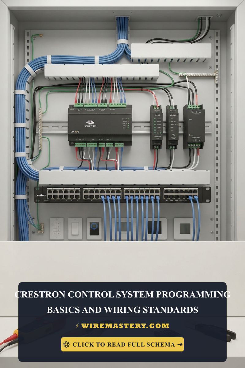
To configure a professional, code-compliant smart home infrastructure network when integrating multiple high-density smart home automation devices, you must establish a centralized distribution node and maintain rigid isolation boundaries between low-voltage digital signal tracks and high-voltage building power loops.
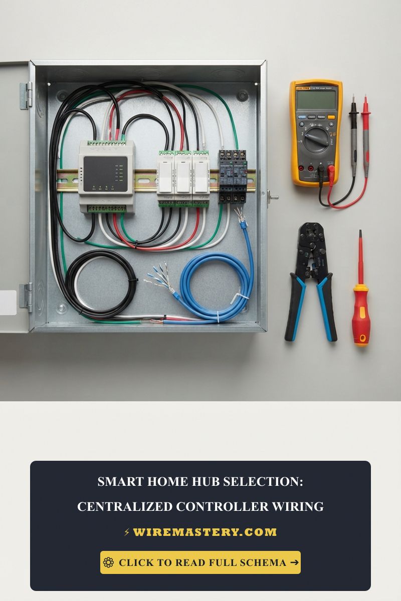
1. Step-by-Step Field Blueprint: Wiring a Centralized DIN-Rail Automation Controller
To wire a replacement high-capacity automated lighting control panel box enclosure safely and cleanly, execute this precise trade sequence on your workstation:
- De-Energize and Isolate Power Loops: Locate your property’s main service distribution panel board. Disengage the dedicated circuit breaker toggle supplying power to the target room box enclosure. Install your padlock lockout safety tagout clamps over both switches. Confirm an absolute 0V state across all terminal contacts using your digital multimeter before wire handling.
- Mounting and Line Terminations: Mount the NEMA 1 rated metallic automation enclosure box securely onto the structural framing wall studs. Secure the centralized DIN-rail automation controller chassis to the rail track. Route your incoming high-voltage 120V line wires directly into the top pressure plates stamped LINE and NEUTRAL. Use your torque wrench to tighten the lug screws to exact manufacturer specs (typically 35 inch-pounds), preventing loose connections that lead to catastrophic arc faults.
- Wire the Low-Voltage Control Logic Signal Matrix: Connect your 24V DC signaling lines coming from your optocoupled automation relay board directly onto the small side terminal screws stamped A1 and A2. Ensure you utilize 23 AWG solid copper Category 6A lines for all data communication buses, maintaining a tight geometric pairing layout to eliminate signal attenuation.
2. Suppressing Electromagnetic Noise with Shielded Twisted-Pair (STP) Cabling
When multiple high-frequency data lines are bundled together inside a single vertical drywall track, the electromagnetic signals leaking out from adjacent tracks can contaminate communication channels, a fault mode classified as Alien Crosstalk (ANEXT).
- The Technical Remedy: Engineers mandate the installation of Shielded Twisted-Pair (STP) cabling for all structural smart home devices backbones. Ensure you bond the outer aluminum foil shielding layer of the cable exclusively to the system’s primary grounding bus bar strip inside the central distribution rack. This explicit connection point establishes a low-impedance ground track that drains high-frequency noise fields straight to earth, preserving signal-to-noise ratios (SNR).
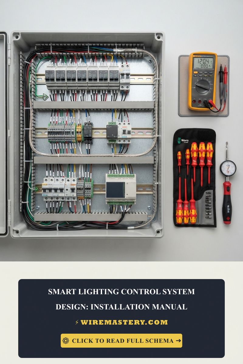
🛠️ The Box Fill Volume Spacing Constraint Note: Look closely at the multi-circuit home automation smart home blueprints displayed throughout our engineering planning portfolios. Notice that packing bulky solid-state smart switches inside a shallow, vintage single-gang wall cavity box is completely illegal. Under the calculation matrices of NEC 314.16(B), these smart devices mandate a double conductor volume deduction based on the supplying wire size to account for their internal logic boards and radio chassis. Always enforce upgrading shallow boxes to deep 22-cubic-inch thermoplastic or metallic box enclosures to prevent wire insulation pinching short circuits during the final seating phase.
Troubleshooting Common Home Automation System Failures
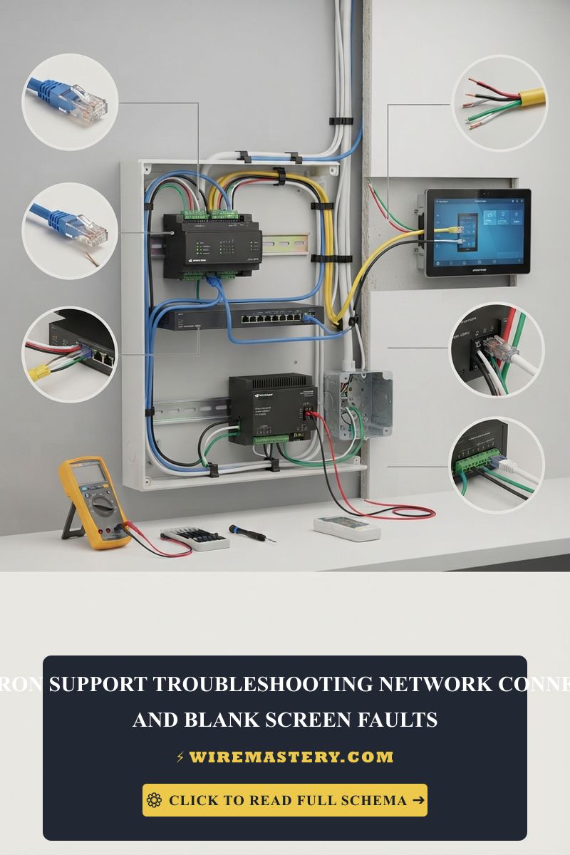
- The Automation Display Screen Flickers or Freezes When Large Appliances Start: This behavior indicates intense Electro-Magnetic Interference (EMI) induction tracking. Your low-voltage data cables were routed too close to unshielded 240V HVAC or water heater lines inside the wall framing, violating NEC Article 800 separation boundaries. The massive inrush current from the starting compressor generates a fluctuating magnetic field that corrupts the digital data streams running through the data line. Re-route the low-voltage communication tracks or pull a certified OM4 multi-mode fiber optic line to clear the interference completely.
- The Smart Switches Module Loses Wi-Fi Connection Whenever the Light is Turned ON: An absolute indicator of an active internal impedance mismatch circuit error. If your lighting load consists of ultra-low-power bulbs totalizing less than 25 Watts overall, turning the internal triac relay on causes the voltage drop across the switch input terminals to collapse below operational parameters. The microprocessor loses logic power, forcing a continuous reboot loop. Install a higher-wattage resistive bulb along the loop or wire a parallel load resistor block to stabilize the standby voltage matrix.
- The Upstream Circuit Breaker Trips Immediately Upon Smart Controller Initialization: This symptom confirms a Dead Short Circuit or a ground fault breakdown inside the box cavity. When stuffing the wire bundles and the bulky smart switch frame into a cramped single-gang box enclosure, an uninsulated bare copper equipment grounding wire can bend and touch a live side brass phase terminal screw plate. Pull the device out using your insulated tools, separate the wire lines, and encapsulate the outlet casing perimeter with high-grade electrical insulation tape.
National Electrical Code Automation Safety Regulations
Adhering to strict national structural regulations protects your smart house infrastructure from electrical fire hazards, maintains full property insurance validity, and ensures complete alignment with federal inspection safety boundaries. Centralized smart home automation platforms, low-voltage control circuits, and communication paths are heavily cross-regulated under NEC Article 800 (Communications Circuits):
- Separation from Power Conductors (NEC 800.133): Communications and low-voltage data cables shall not be placed in any raceway, compartment, outlet box, junction box, or similar fitting with conductors of electric light, power, or Class 1 circuits. Data paths entering a shared wall box housing high-voltage switches must be isolated completely behind approved metallic dividers or non-combustible barrier sleeves, preventing line voltage leaks from entering low-voltage logic displays.
- The Component Listing Mandate (NEC 110.3(B)): Every single smart for home asset integrated into the building envelope must be officially listed and labeled by an approved, independent testing laboratory (such as UL, Intertek, or CSA) and utilized strictly in full compliance with the explicit technical instructions printed on the product casing.
For the NFPA 70 provisions relevant to this guide on Top Smart Home Automation Devices: Contractor Installation Guide, consult the Official NFPA 70: National Electrical Code (NEC).
Conclusion
This article explains low-voltage data signaling tracks, executing centralized automation controller setups on structural DIN rails, and controlling electromagnetic noise parameters under strict NEC Article 800 boundaries transforms complex smart home upgrades into highly controlled, predictable sciences. By keeping conductor gauges fully aligned with continuous continuous overcurrent limits under NEC Table 310.16, eliminating dangerous siphoning shortcuts across exposed metallic yokes, and enforcing absolute compliance with UL listing guidelines, you build an exceptionally resilient, safe automated residential infrastructure. For final checks, complete panel breaker power isolation safety checkups before opening junction boxes, deploy CAT III certified diagnostic meters, and complete every mechanical terminal connection step with precision.