Why Are Lights Flickering in My House? Safety Diagnostics
Isolating and resolving structural voltage fluctuations that cause residential luminaires to blink, dim, or strobe intermittently requires a planned technical roadmap combining physical conductor audits, panel terminal inspections, and diagnostic meter analysis. While isolated, fractional light flickering can occasionally point to a failing bulb driver, widespread or systemic multi-branch circuit flickering indicates an active and potentially volatile electrical anomaly rooted within the property’s distribution layout. For properties protecting delicate server equipment, home automation controllers, or critical networking nodes against these harsh line sags, integrating a high-performance battery backup for home office and surge system layout provides an unshakeable barrier that conditions volatile line feeds.
The structural engineering causes behind systemic flickering, the severe electrical fire hazards associated with a broken main neutral pathway, and diagnostic voltmeter testing sequences.
Core Circuit Engineering Thresholds
Before removing structural deadfront panel shields or pulling terminal wires forward from device enclosures, decode these foundational thresholds:
- The Systemic Voltage Variance Limit: Under standard North American utility infrastructure guidelines, a stable single-phase nominal 120V AC branch loop must stay within an active operational tolerance window of ±5% (114V AC to 126V AC) under full structural load constraints.
- The Open Neutral Emergency Point: A loose, corroded, or severed main service neutral line transforms a balanced multi-wire distribution system into an unstable, floating load matrix. This structural failure causes the line-to-neutral voltage on one 120V phase to sag toward 0V while simultaneously forcing the opposing 120V phase to skyrocket up toward 240V AC, instantly frying electronic power supplies and creating active fire conditions.
- The LED Driver Inrush Phenomenon: Modern solid-state light-emitting diode (LED) arrays require specialized dimming interfaces. Deploying legacy resistive analog rheostat switches on capacitive LED power inputs triggers severe phase-angle chattering, causing high-frequency strobe artifacts.
Technical Materials & Volatage Fluctuations Auditing Toolkit
Safely tracking high-amperage phase imbalances and measuring physical conductor resistance parameters requires specific testing equipment and insulated trade hand tools:
| Electrical Auditing Tool | Primary Engineering Purpose & Safety Threshold |
|---|---|
| True RMS Digital Multimeter | Category CAT III 600V minimum to capture real-time min/max voltage sags across energized terminals. |
| Non-Contact AC Voltage Detector | Audibly verifies full circuit isolation inside subpanel and switch enclosures before bare handling. |
| Insulated Linesman Screwdrivers | Cushion-grip drivers rated for 1000V AC to torque down terminal blocks and panel lugs safely. |
| Plug-In Receptacle Loop Tester | Plugs directly into branch outlets to instantly visualize hot/neutral/ground wiring configuration faults. |
| Infrared Thermal Laser Thermometer | Pinpoints high-resistance localized hotspots over circuit breaker casing lines without physical contact. |
The Diagnostics Phase: Tracking Down the Scope of the Flicker Anomalies
Technicians must systematically map out the physical boundary zone of the electrical instability before uncoupling wires. Never execute random component replacements without confirming the fault footprint:
Scenario A: The Instability is Confined strictly to a Single Fixture
If only one light bulb or track system blinks while the remaining luminaires inside the same room run perfectly flat, the failure is localized.
- The Culprit: The issue points to an oxidized bulb socket tab, a failing LED driver board, or an incompatible dimmer chip trailing edge connection.
Scenario B: The Instability Impacts a Single Complete Branch Circuit
If every light fixture and wall outlet inside a dedicated bedroom or kitchen zone dims simultaneously when a specific device engages, you are dealing with a localized line load issue.
- The Culprit: This pattern indicates an overloaded branch circuit loop or a loose wire nut splice connecting the daisy-chained Romex lines inside a junction box down the line.
Scenario C: The Instability Shakes the Entire Residential Structure
If lights across completely different rooms, floors, and breaker phases flicker simultaneously, or if the lights dim dramatically whenever the outdoor AC compressor or refrigerator launches, you are facing a severe main supply panel issue.
- The Culprit: This pattern indicates high-resistance master panel main breaker lugs, a failing utility pole step-down transformer connection, or a disintegrating main service entrance neutral path.
Technical Phase: Executing an Open Neutral Voltmeter Diagnostic
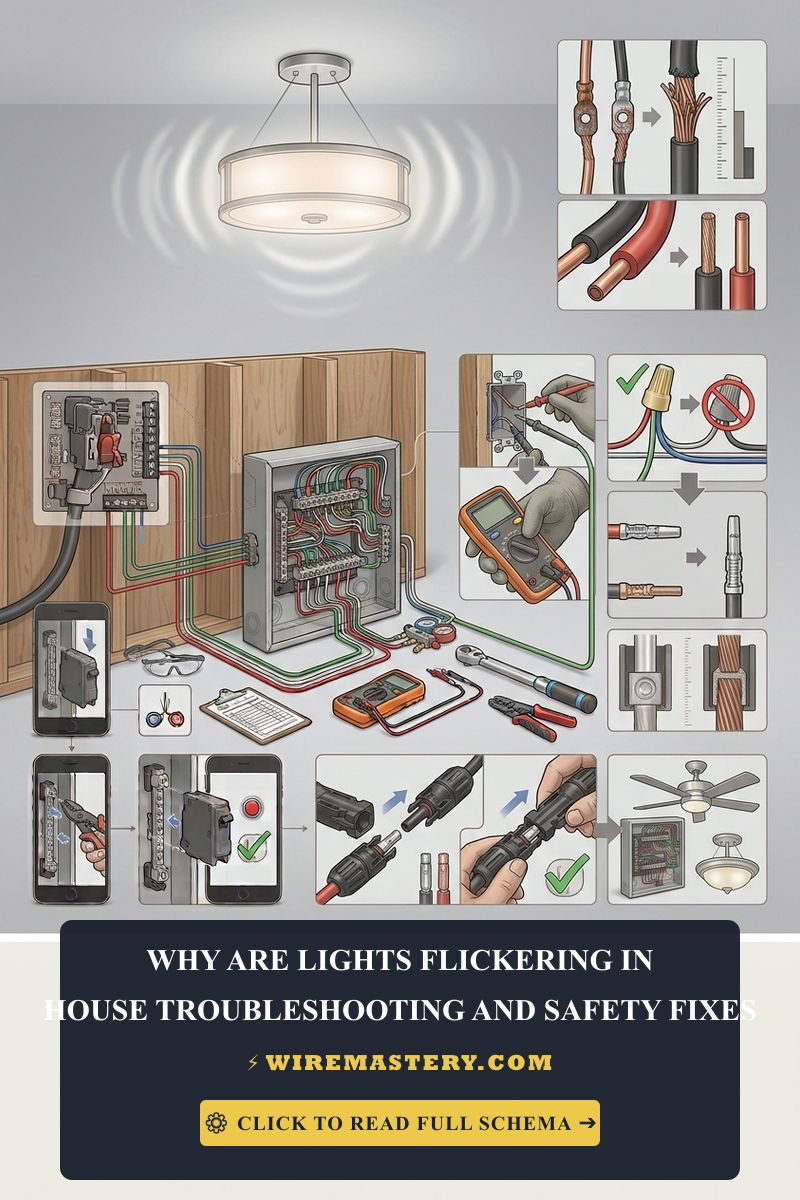
If your observation phase reveals structural, house-wide flickering where some lights get blindingly bright while others drop to a faint orange glow, you must immediately audit your master service lugs using a digital multimeter to confirm if your primary neutral return path has failed:
The Phase-to-Neutral Balancing Audit
- Put on your ANSI-rated safety glasses and high-dielectric insulated work gloves. Remove the master service panel outer deadfront shield carefully to expose the main feed lugs coming from the utility meter box assembly.
- Rotate your digital multimeter dial to the AC Voltage setting (V AC).
- Place your black testing probe firmly onto the center silver Main Neutral Bus Bar Lug. Place your red testing probe onto the top left Phase A Main Hot Lug. Note the digital reading.
- Keep the black probe anchored on the neutral bus bar and move the red probe down to the Phase B Main Hot Lug. Note the second reading.
- Analyze the Balancing Parameters:
- A Healthy Core System: Both Phase A and Phase B will display matching, stable readings between 115V AC and 121V AC.
- An Active Open Neutral Fault: Phase A might display an elevated reading of 145V AC, while Phase B drops simultaneously down to 95V AC. Turn off your house main disconnect breaker immediately. This severe imbalance confirms your main neutral path is broken, and continuing to run current will destroy your property’s electronics and trigger immediate structural arc fires.
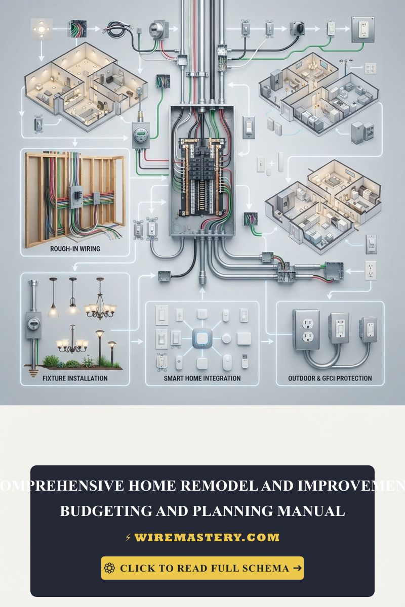
🛠️ Panel Lug Thermal Maintenance Note: Look closely at the industrial distribution schematics showcased throughout our structural wiring portfolios. Notice that main panel connection lugs are subject to continuous thermal cycling stress under heavy seasonal utility draws. Over years, this micro-expansion causes aluminum service wires to cold-flow, loosening the terminal clamp’s physical grip. Always execute a non-contact infrared thermal laser sweep over your primary breaker panel casing line; an un-insulated terminal lug registering a localized heat signature spike above 140°F (60°C) requires an immediate torque calibration to eliminate progressive flickering.
Step-by-Step Restoration Manual for Flickering Lighting Circuits
1. Resolving Incompatible LED Dimmer Chattering
If your room-wide LED retrofits strobe or hum aggressively whenever you lower the wall toggle position, you have a component mismatch:
- Isolate the branch panel breaker and pull the switch out of the gang box enclosure.
- Inspect the rear casing stamps. Standard analog incandescent switches slice the AC voltage wave on the forward leading-edge, which chokes the internal smoothing capacitors of digital LED bulb drivers.
- Replace the legacy unit with a certified Electronic Low-Voltage (ELV) or True Reverse-Phase Dimmer module explicitly listed for LED driver loads. Ensure you program the low-end trim adjustment option on the hidden software face of the switch body to lock out the low-voltage cutoff threshold where flickering naturally builds up.
2. Splicing Loose Daisy-Chained Romex Connections
If your diagnostic mapping isolates the flickering loop to a single bedroom branch circuit, a loose connection inside a junction box down the track is creating a high-resistance hotspot:
- De-energize the branch loop breaker and confirm a absolute 0V AC state using your non-contact tester.
- Open the junction enclosures located along the circuit run one by one. Locate the neutral white bundles wrapped in economy wire nuts.
- Unscrew the loose connectors. If you see signs of minor tracking or scorched copper tips, use your high-leverage lineman pliers to snip back the brittle sections until reaching shiny pink copper.
- Hold the wire ends side-by-side and use your pliers to twist the solid copper shanks into a tight, uniform mechanical helix loop before capping the assembly with a brand-new, heavy-duty twist-on wire nut.
National Electrical Code Infrastructure & Safety Standards
Adhering to strict national structural regulations protects your home infrastructure from fire hazards and ensures full property insurance compliance. The National Electrical Code strictly regulates general grounding networks, load distributions, and service panel terminations under NEC Article 230 (Services), Article 250 (Grounding and Bonding), and Article 404 (Switches):
- Main Service Bonding Mandates (NEC 250.24): The grounded service conductor (Main Neutral) must be connected to the equipment grounding conductor and bonded directly to the main service enclosure box steel via an approved main bonding jumper screw. This mandatory link provides a stable zero-potential ground reference across all internal branch loops, stabilizing line voltage sags.
- Switch Rating Compliance (NEC 404.14): All dimmer switches controlling solid-state lighting arrays must be officially listed and explicitly rated for the electronic LED load types they supply to avoid internal gate-turn-off switching failures that trigger intense line harmonics.
For the NFPA 70 provisions relevant to this guide on Why Are Lights Flickering in My House? Safety Diagnostics, consult the Official NFPA 70: National Electrical Code (NEC).
Conclusion
This article explains residential voltage variances, executing main neutral bus bar multimeter audits, and replacing incompatible analog dimming modules with modern reverse-phase hardware transforms chaotic lighting problems into clean, solutions. By keeping line fluctuations within strict code tolerances, realigning loose wire nut splices inside junction boxes with high-leverage pliers, and respecting mandatory NEC service grounding boundaries, you build an unshakeable, resilient home grid infrastructure. For final checks, complete panel power isolation safety checks, utilize CAT III multimeters, and complete every diagnostic step with precision.