How to Wire a 3-Way and 4-Way Switch (Complete Diagram Guide)
Expanding a residential multi-location lighting network to control a single load from three or more distinct wall boundaries demands a comprehensive understanding of serial lighting loops and alternating traveler configurations. While a standard 3-way switch setup satisfies basic dual-point controls—such as the top and bottom of a standard stairwell—introducing additional command nodes requires incorporating a dedicated 4-way switch module. A 4-way switch operates as an internal crisscross toggler that alters the electrical current path between two flanking 3-way units. Executing these terminations poorly or misidentifying terminal pairs will break the circuit continuity loop, causing erratic switch dead zones.
Structural 4-way lighting layouts, traveler input/output terminal matrices, and National Electrical Code (NEC) load safety calculation frameworks.
Core Circuit Engineering Thresholds
Before unmounting device hardware or routing continuous multi-conductor sheaths through studs, verify these structural criteria:
- The Flanking Constraint: A 4-way switch cannot function as a standalone device or interface directly with the main power panel line. It must be positioned physically and electrically strictly in between two standard 3-way switches.
- Terminal Mechanical Layouts: Unlike 3-way units equipped with a single common terminal screw, a 4-way switch features four terminal screws (typically brass and black, or distinctly paired) plus a green safety grounding screw.
- Conductor Profile Requirements: The wiring harness interconnecting the switch enclosures must utilize three-conductor sheathed cables (such as 14/3 or 12/3 NM-B Romex) to provide a dedicated dual-traveler highway alongside a continuous neutral line.
Technical Materials & Rough-In Diagnostic Toolkit Checklist
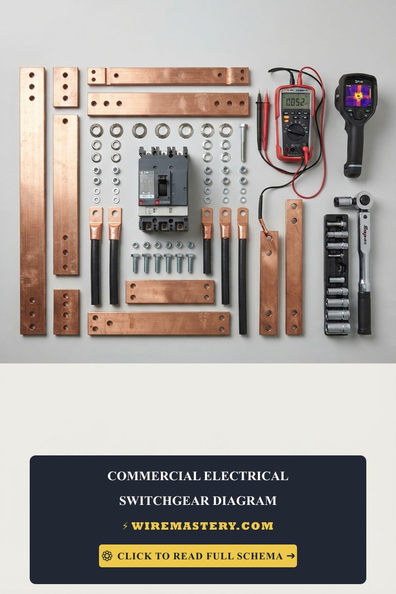
Safely identifying, routing, and terminating high-density multi-location lighting conductors requires specific industrial trade hand tools and insulated testing instrumentation:
| Electrical Trade Tool | Primary Technical Purpose & Field Application |
|---|---|
| Non-Contact AC Voltage Tester | Essential instrument used to verify 100% circuit de-energization inside deep gang box cavities. |
| Digital Auto-Ranging Multimeter | Measures true AC line voltages (0V to 130V) to pinpoint active incoming power lines. |
| Ratcheting Solid Wire Strippers | Calibrated to shear outer PVC protective casings cleanly off #14 AWG and #12 AWG copper conductors. |
| Ergonomic Needle-Nose Pliers | Formulates uniform, tight clockwise conductor hooks to wrap neatly around device side screws. |
| UL-Listed Twist-On Wire Nuts | Heavy-duty insulated wire connectors to secure high-density neutral bundles and ground pigtails. |
The American Wire Gauge (AWG) Ampacity Matrix
To eliminate the risk of localized resistance and dangerous thermal heat accumulation behind finished drywall sheets, you must select the correct copper wire gauge matching your overcurrent panel breaker rating. Underloading or matching thin wire profiles to heavy breakers violates safety standards under NEC Article 310.16:
| Circuit Amperage Limit | Required Wire Gauge (AWG) | Standard Romex Jacket Color | Primary Lighting Loop Context |
|---|---|---|---|
| 15 Amps | 14 AWG Solid Copper (14/2 & 14/3) | White | Standard residential lighting layouts, smoke alarms, and bedrooms. |
| 20 Amps | 12 AWG Solid Copper (12/2 & 12/3) | Yellow | Kitchen task lighting, commercial layouts, and heavy multi-fixture arrays. |
Understanding the 3-Way Switch Foundation
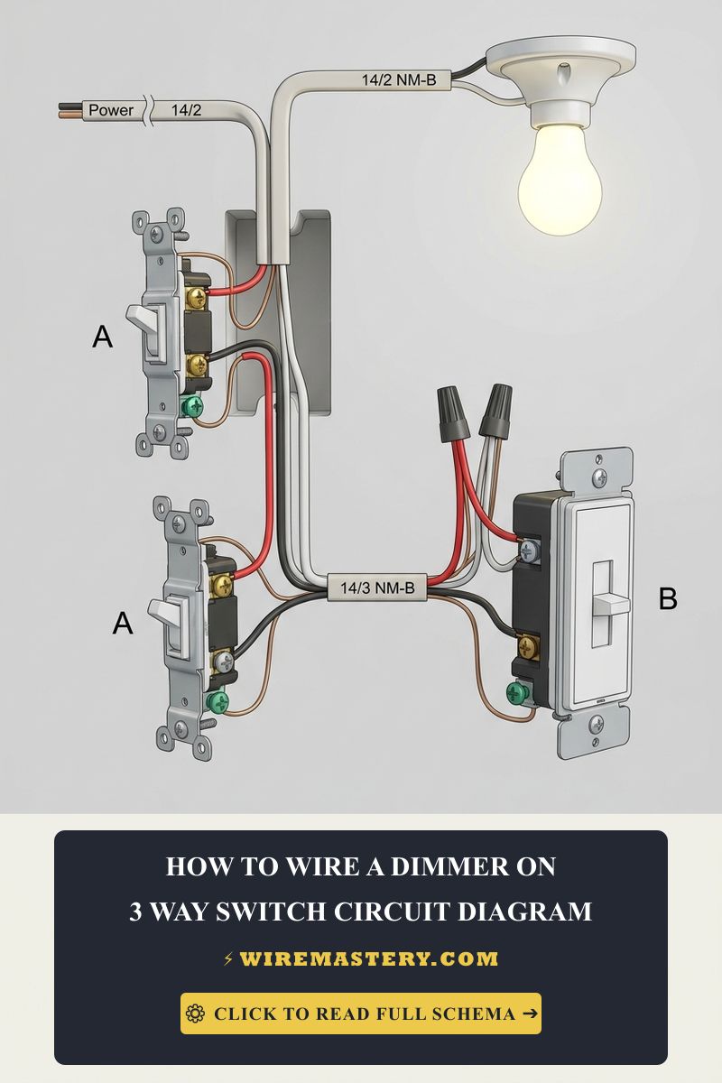
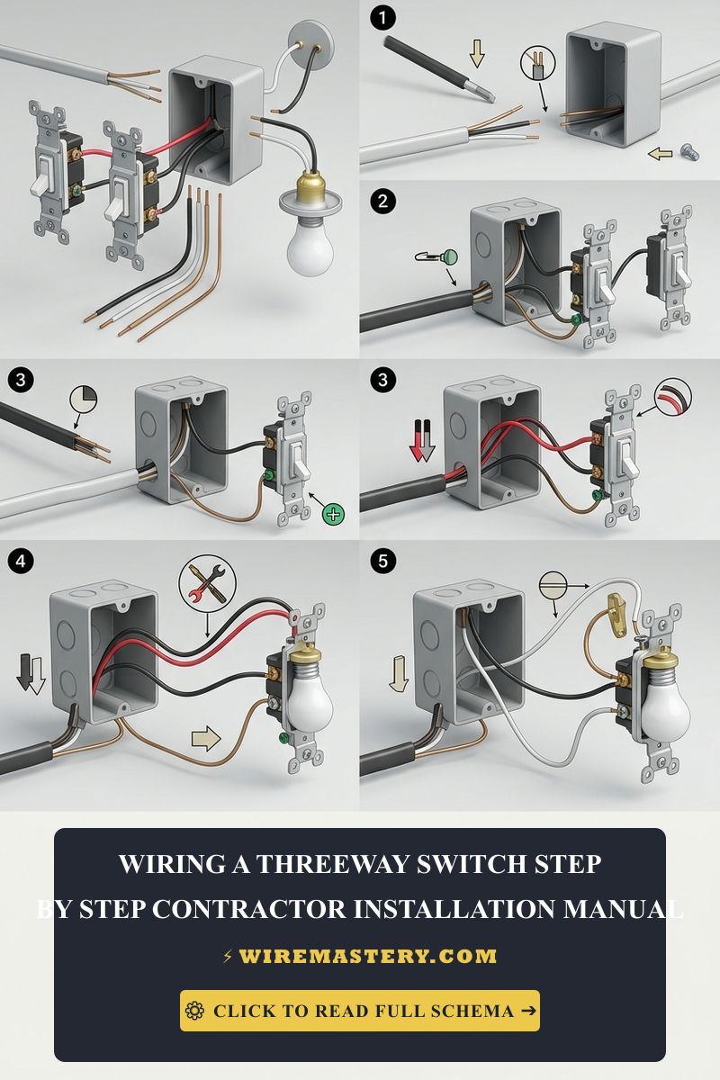
Before integrating a 4-way center node, you must master the standard 3-way switch circuit. A 3-way system relies on a common terminal (connected to line power or the load) and two traveler terminals that alternate paths. When a homeowner asks how to wire a 3-way switch, they are establishing the mandatory dual-point foundation required before any multi-location 4-way expansion can occur.
The Structural Mechanics of a 4-Way Switch Diagram
The most common installation error made by field apprentices is crossing the incoming traveler pair with the outgoing traveler pair on the switch body. To read a 4-way switch circuit schematic accurately, you must categorize the terminals into input and output gates based on manufacturer stamps rather than screw height.
To review how these multi-location line extensions tie into dual-point foundations, consult our master blueprint on 3-way switch wiring diagrams and contractor guidelines.
Official 4-Way Receptacle Switch Terminal Mapping
| Terminal Screw Label / Color | Source Origin Conductor | Circuit Technical Role & Internal Logic |
|---|---|---|
| Input Terminals (Line Side / Brass) | 14/3 or 12/3 Travelers from Switch 1 | Accepts the alternating current toggles coming from the first 3-way box. |
| Output Terminals (Load Side / Black) | 14/3 or 12/3 Travelers to Switch 3 | Routes the modified alternating current loops down to the final 3-way box. |
| Green Hex Screw / Ground Strap | Bare Copper / Green Insulated Conductor | Redirects dangerous chassis leakage currents safely away to the panel earth bar. |
Step-by-Step 4-Way Multi-Location Installation Manual
Executing a 4-way installation requires running conductors through a three-box configuration layout. Follow this systematic trade deployment sequence to ensure full circuit continuity:
1. Pre-Installation Power Isolation Protocol
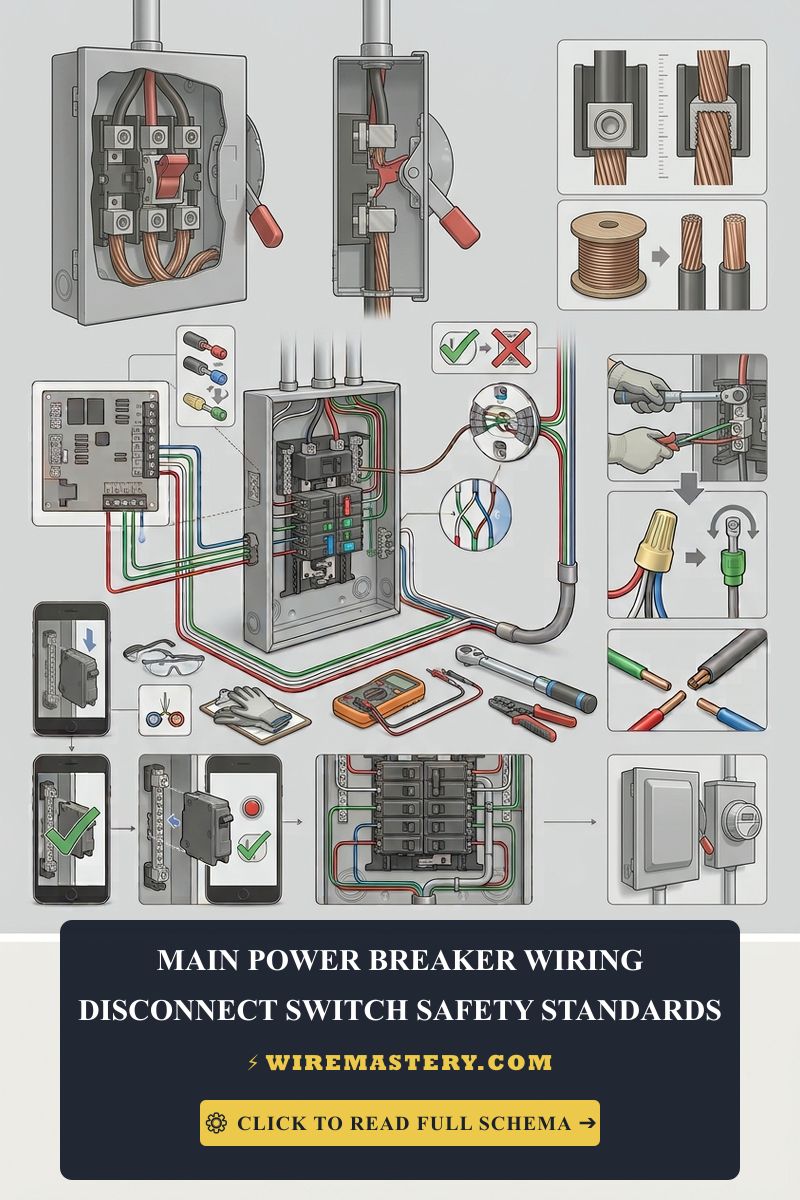
Locate your property’s primary distribution panel board. Turn off the circuit breaker feeding the lighting branch and verify the box cavity reads completely dead (0V AC) at all three wall locations using your non-contact voltage tester before backing out any mounting ears.
2. Wiring Box 1: The Primary 3-Way Switch (Line Side)
Box 1 contains the incoming source cable coming straight from the breaker panel box.
- Connect the raw 120V Line Hot wire (Black) directly to the Dark Common terminal screw on the first 3-way switch assembly.
- Connect the Black and Red conductors of the outgoing 14/3 or 12/3 Romex traveler bundle to the two lighter brass traveler screws.
- Tie the white neutral wires from the panel feed and the outgoing traveler cable together using a UL-listed wire nut. Do not hook them to the switch body.
3. Wiring Box 2: The Core 4-Way Switch Center Node
Box 2 receives the 14/3 or 12/3 cable from Box 1 and routes an independent 14/3 or 12/3 line to Box 3.
- Locate the two traveler wires originating from Box 1. Secure them directly to the two Input brass terminal screws (typically labeled LINE 1 or IN).
- Locate the two traveler wires running out toward Box 3. Secure them to the two Output dark terminal screws (labeled LOAD 1 or OUT).
- Wire-nut the current-carrying white neutral wires together to maintain unbroken neutral continuity across the entire circuit path. Secure all bare copper safety grounds to the green grounding screw block.
4. Wiring Box 3: The Final 3-Way Switch (Load Side)
Box 3 houses the cable harness leading directly to the physical light bulb socket fixture.
- Connect the Load Hot wire (Black) running to the light fixture directly to the Dark Common terminal screw of the remaining 3-way switch.
- Secure the two traveler wires incoming from the Box 2 center node to the two lighter brass traveler terminals.
- Tie the white neutral wire from the light fixture directly to the white neutral wire traveling from Box 2 using a twist-on wire connector to close the circuit loop.
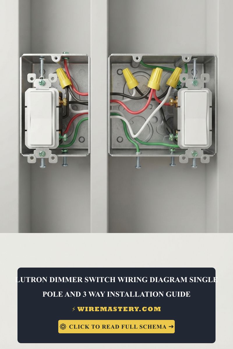
🛠️ Drywall Volume Clearance Note: Look closely at the multi-gang box installations displayed throughout our electrical design portfolios. Notice that a 4-way switch body features a bulkier mechanical footprint than standard toggle hardware. When folding your thick #12 AWG solid copper conductor wires back into the wall box cavity, always utilize an alternating accordion folding pattern. Jamming or forcing wires in haphazardly risks shaving off nylon insulation coatings against sharp box edges, triggering dead short circuits behind the wall framing.
Troubleshooting Multi-Location Switch Inversions
- The Light Only Toggles from Specific Switch Combinations: This behavior indicates a dead zone caused by a crossed traveler pair fault. You have accidentally wired one incoming traveler wire onto an output terminal, or vice versa, on the 4-way switch body. Disengage the panel breaker, pull the center switch forward, and verify that the two lines traveling inside the same Romex jacket from Box 1 anchor exclusively to the paired input terminals.
- The Breaker Tripps Instantly When the Light Turns On: This indicates an active dead short circuit. It typically happens when an installer leaves too much raw copper exposed past the side terminal screws. When pushing the bulky 4-way switch into a metal gang box enclosure, the exposed copper touches the grounded chassis. Wrap the entire perimeter of the switch body using two tight layers of high-grade electrical tape to fully insulate the side screws.
- Modern LED Bulbs Glow Faintly when Switched Off: High-density traveler runs extending past 70 feet inside the same wall cavities can experience inductive voltage bleeding. The close physical proximity of the conductors creates a capacitive coupling effect that induces a tiny current track down the line. Swap the bulbs for high-quality models equipped with internal bleed resistors, or install a Lutron LUT-MLC bypass capacitor across the light load leads.
National Electrical Code Compliance Standards
Adhering to strict construction codes ensures your home infrastructure remains legal, fully insurable, and structurally safe. The National Electrical Code strictly regulates multi-location switch loops under NEC Article 404 (Switches) and the sizing parameters of Article 314:
- The Grounded Conductor Mandate (NEC 404.2(C)): Modern electrical codes dictate that a continuous grounded neutral conductor (White wire) must be present at each switch location within the loop. This ensures that if a homeowner decides to upgrade to smart home automation switches or motion sensors in the future, the device has a built-in neutral return path to power its internal processors safely without illegally bleeding current down the ground wire.
- Box Fill Volume Capacities (NEC 314.16): Because 4-way switch boxes house multiple incoming and outgoing multi-conductor cable sets, they are highly prone to overcrowding code violations. Conduct a strict box volume calculation based on NEC Table 314.16(B) to determine if you need to upgrade to a deep 22-cubic-inch box enclosure to avoid dangerous wire pinching.
For the NFPA 70 provisions relevant to this guide on How to Wire a 4-Way Switch: Circuit Diagram & Installation Guide, consult the Official NFPA 70: National Electrical Code (NEC).
Conclusion
This guide covers calculating box fill capacities and executing a 4-way switch circuit installation steps up your electrical troubleshooting capabilities and ensures optimized home safety across your residential grid. By tracking input vs. output traveler pairs with an auto-ranging multimeter, enforcing matching AWG copper wire colors, and respecting mandatory NEC neutral wire presence boundaries inside wall cavities, you build a resilient, commercial-grade electrical framework. For final checks, complete circuit breaker power isolation testing, utilize certified diagnostic instruments, and complete every terminal step with safety-first care.