3-Way Switch Wiring Diagram
Mastering the exact connection paths across multi-point residential lighting branch networks requires looking past basic hardware diagrams. For installers evaluating real-world field schematics, deploying a certified, code-compliant diagram on how to wire a three way switch ensures clean traveling path isolation, zero voltage attenuation, and strict compliance under National Electrical Code mandates.
Controlling a residential lighting load from two separate wall locations requires a planned multi-location branch circuit covering traveler routing, box capacities, and NEC regulations. For advanced setups protecting sensitive equipment or home automation hubs, integrating an industrial-grade battery backup for home office configuration ensures continuous operation and surge protection.
The mechanical terminal layouts, traveler line tracing methodologies, and National Electrical Code (NEC) boundaries required to wire a 3-way switch safely.
Core Circuit Engineering Thresholds
Before removing your existing toggles, establish your structural branch parameters:
- The Common Terminal Rule: Every 3-way switch features one uniquely colored screw (typically dark charcoal or black) known as the Common terminal. This screw anchors the incoming 120V live feed in Box 1, or routes the output load line to the light fixture in Box 2.
- The Traveler Highway: The two lighter brass screws manage the traveler lines (running inside a 14/3 or 12/3 Romex bundle). These lines alternate carrying current between the two switch locations.
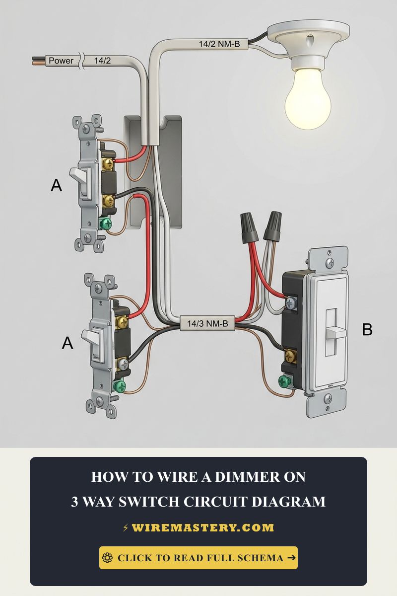
- Device Matching Constraints: You cannot install two dimmers on the same 3-way loop unless they are specialized digital smart companion switches. Standard analog dimmers will fight each other for voltage dominance, causing severe LED flickering.
Technical Materials & Diagnostic Testing Checklist
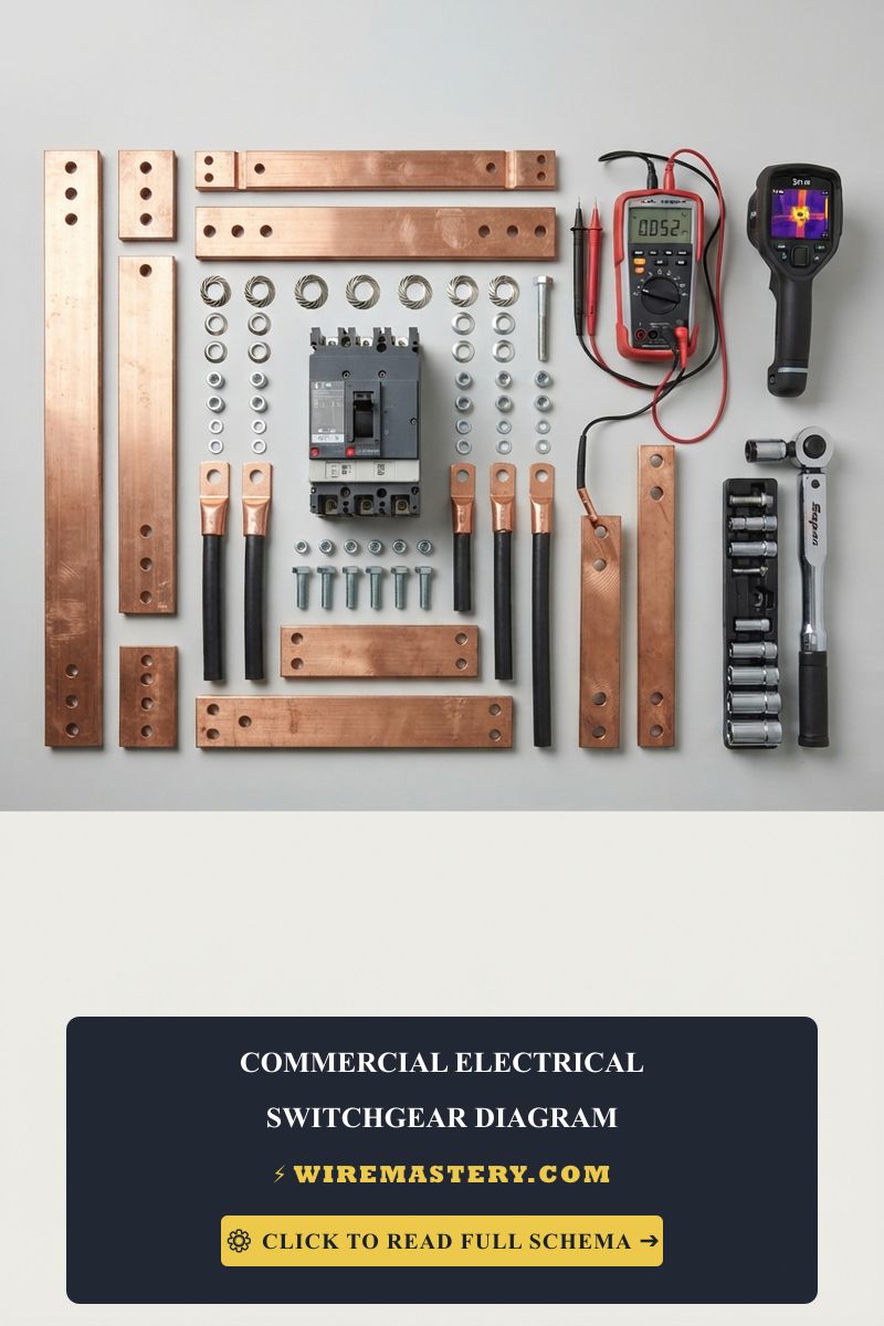
Executing a clean, code-compliant multi-location installation requires specific trade tools and safety equipment:
| Electrical Trade Tool | Primary Technical Purpose |
|---|---|
| Non-Contact Voltage Detector | Crucial tool to verify 100% circuit de-energization before touching side screw terminals. |
| Digital Auto-Ranging Multimeter | Measures exact AC voltage parameters to trace live common feeds from the panel board. |
| Ergonomic Wire Strippers | Calibrated to shear outer PVC sleeves cleanly off 14 AWG and 12 AWG solid copper cores. |
| UL-Listed Wire Nuts | Heavy-duty twist-on connectors to tie neutral bundles and grounding pigtails together securely. |
| Precision Pocket Level | Ensures the switch body mounts perfectly straight for final faceplate alignment. |
The American Wire Gauge (AWG) Ampacity Matrix
To avoid dangerous heat accumulation behind finished walls, you must match your structural wire size to the corresponding circuit breaker rating. Over-sizing your copper lines is perfectly safe, but under-sizing a conductor violates federal building codes under NEC Article 310.16:
| Circuit Amperage | Required Wire Gauge (AWG) | Standard Romex Jacket Color | Primary Lighting Application |
|---|---|---|---|
| 15 Amps | 14 AWG Solid Copper (14/2 & 14/3) | White | Standard residential lighting branches and bedroom zones. |
| 20 Amps | 12 AWG Solid Copper (12/2 & 12/3) | Yellow | Commercial layouts, high-wattage arrays, and laundry nodes. |
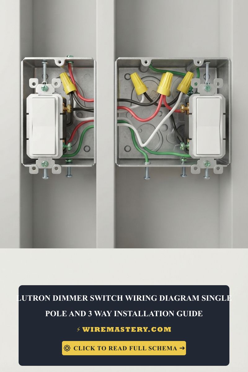
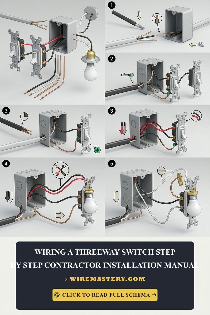
🛠️ Contractor Blueprint Reality Check: Look closely at the standard 3-way switch layouts printed across technical guides. Notice how the individual travelers change positions depending on the toggle toggle states. When tracking an unlabelled field bundle, never guess conductor pathways based on insulation colors alone. Always trace the line back to its labeled terminal block anchor point to avoid blowing the panel’s 3-amp blade fuse.
Step-by-Step 3-Way Switch Installation Manual
1. Circuit Isolation and De-energization
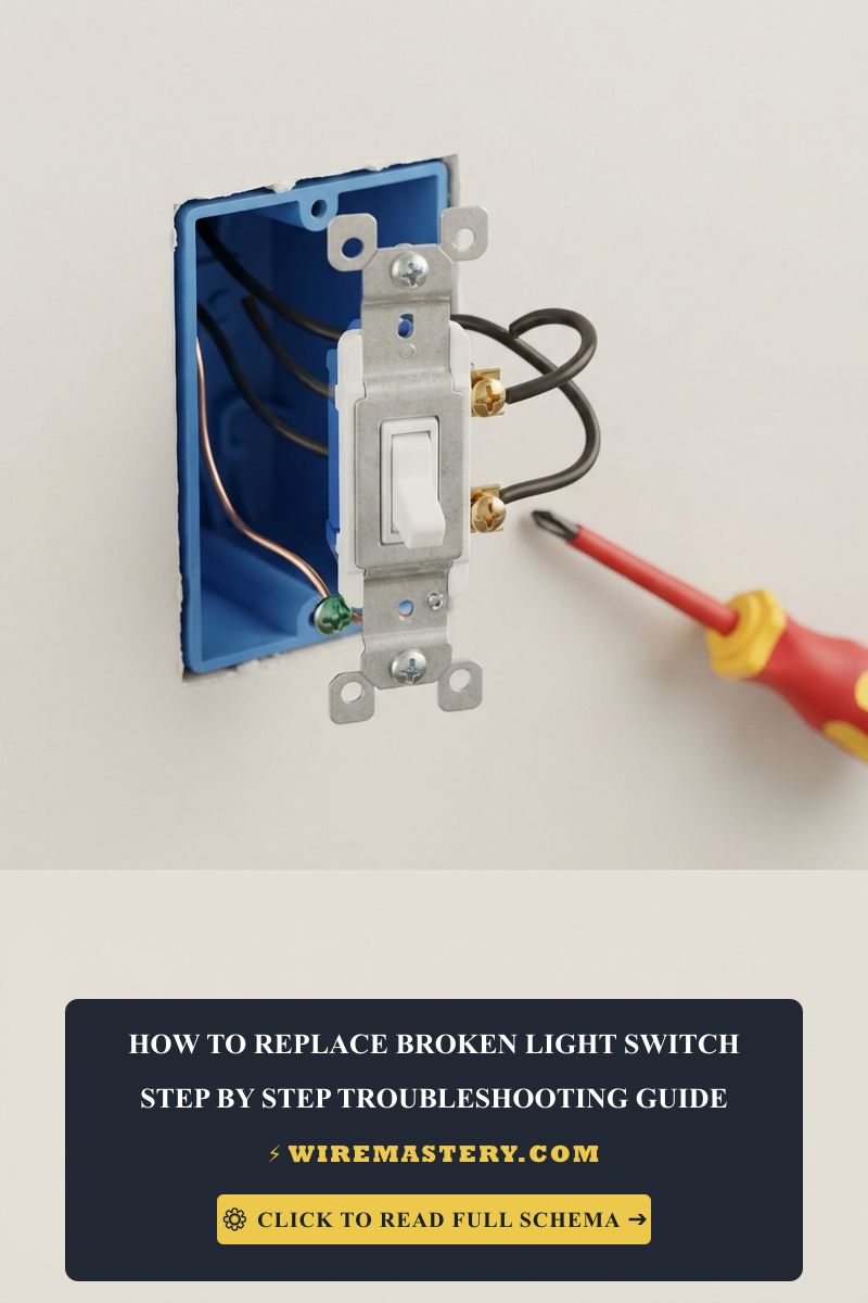
Locate your property’s primary breaker panel and disengage the switch feeding the workspace area. Remove the decorative faceplates at both wall locations. Prior to backing out any screws, press your non-contact voltage tester against every wire to confirm the box cavity reads completely dead (0V AC).
2. Identifying and Tagging the True Common Line
If you are dealing with an unlabelled mess of wires inside the wall, use this trade troubleshooting trick to locate your source:
- Pull both old switches forward out of their boxes, keeping all wires attached to the side screws.
- Turn the circuit breaker back ON safely. Do not touch any exposed metal components.
- Hold your digital multimeter probes between the ground wire and each of the three screws on Switch 1. Note which screw registers 120V AC.
- Flip the toggle on Switch 2 and test Switch 1 again. The screw that registers 120V continuous power regardless of the opposing switch position is your Line Common. Tag it with black tape. Turn the breaker back off immediately.
3. Terminating the Primary 3-Way Switch (Box 1)
You will install your first switch in the box containing the tagged common line that originates from the breaker panel:
- Connect the Tagged Line Common wire (Black) directly to the Dark Common terminal screw (labeled COM) on your switch.
- Take the remaining two wires from the box—your Traveler lines (typically one Red and one Black traveling inside the same 14/3 or 12/3 Romex sheath)—and secure them to the two lighter brass traveler screws. The order of these travelers does not impact circuit logic.
- Tie the white neutral wires from the panel feed and the outgoing load cable together using a UL-listed wire nut. Do not connect them to the switch.
- Secure your Bare copper ground wire to the green grounding hex screw on the switch’s metallic mounting bracket.
4. Wiring the Secondary 3-Way Mechanical Switch (Box 2)
Move to Box 2, which contains the multi-conductor cable running directly up to the actual light fixture (the Load Hot).
- Connect the Load Hot wire (which was secured to the dark screw on the old switch assembly) directly to the Dark Common screw (COM) of the second 3-way switch.
- Connect the two traveler wires coming from Box 1 directly to the two lighter brass traveler terminals on the side of the switch.
- Fold the solid copper lines into an alternating accordion pattern back into the plastic gang boxes. Torque the mounting ears flush, align them with your pocket level, and screw on your faceplates.
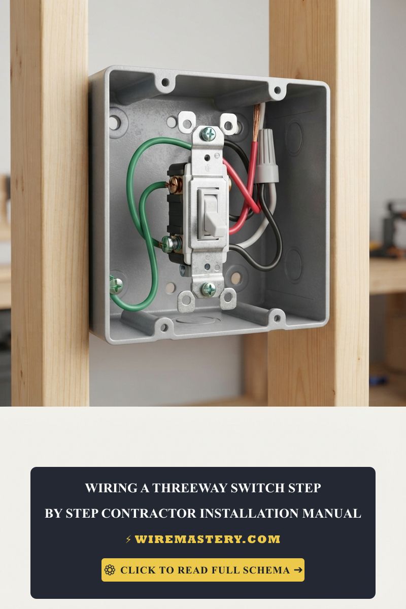
When executing rough-in cable routing steps through vertical wall framing studs, apprentices must track wire terminations to avoid common line cross-connections. Referencing a professional-grade diagram on how to wire a three way switch prevents dangerous hot-to-neutral short circuits, ensuring your traveler conductors land square onto the brass terminal plate screws.
Troubleshooting Common Multi-Location Wiring Faults
- The Switch Only Works When the Opposing Toggle is UP: This is the absolute signature symptom of a crossed traveler and common line fault. You have accidentally wired a traveler line onto the dark common screw in one of the boxes. Disengage the breaker, re-test your lines with your auto-ranging multimeter, and verify the true hot source or load line is anchored exclusively to the dark terminal pin.
- The Circuit Trips the Breaker Instantly When Flipped ON: This indicates a dead short circuit. It typically happens when the bare copper grounding wire makes physical contact with the brass side terminals when pushing the switch back into a tight or overcrowded gang box. Wrap the side perimeter of the switch body with two layers of electrical tape to insulate the screws completely.
- The Light Bulb Flickers or Stays Dimly Lit: If you are using modern LED fixtures on a 3-way loop with an older dimming module, the small leakage current will cause driver chattering. Ensure your hardware is explicitly labeled as a True RMS dimming device and that your LED bulbs are certified as dimmable.
NEC Compliance & Smart Automation Standards
Adhering to strict national structural regulations protects your home insurance coverage and prevents fire hazards inside finished walls. The National Electrical Code strictly regulates multi-location switch loops under NEC Article 404 (Switches) and the structural sizing parameters of Article 314:
- The Mandatory Neutral Rule (NEC 404.2(C)): Modern residential building codes dictate that a grounded neutral conductor (White wire) must be present at each switch location. This ensures that if a homeowner decides to upgrade to smart home automation switches or motion sensors in the future, the device has a built-in neutral return path to power its radio frequency chips safely without illegally bleeding current down the ground wire.
- Box Fill Volume Capacities (NEC 314.16): Multi-location wiring requires feeding 14/3 or 12/3 cables, which increases the wire count inside the box. Ensure you utilize deep 22-cubic-inch boxes to avoid dangerous wire pinching and premature insulation breakdown.
Conclusion
Successfully sorting alternating current paths across multi-point loops requires absolute precision during rough-in packing steps. If your architectural blueprints scale past two standard boundaries to include comprehensive automated spaces, standard multi-conductor cables must route through deep enclosures. Ensure your field trade operations align with our structural reference on certified electrical contractor selection criteria and change order compliance matrices to guarantee your hardware passes city building inspections on the first walkthrough.