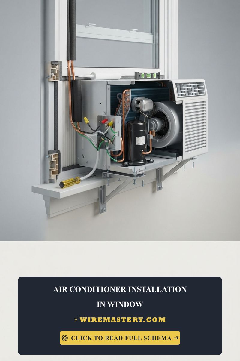
Window Air Conditioner Installation: Step-by-Step Guide
Installing a window air conditioner safely requires checking the window frame, the manufacturer’s support requirements, weather seals, drainage path, and electrical supply before lifting the unit into place. The unit must be supported according to its installation manual; never rely on the sash or interior trim alone to carry the chassis weight.
Before connecting the appliance, verify the receptacle, breaker, grounding, and circuit requirements against the unit nameplate and manufacturer’s instructions. For general conductor information, see our NEC 310.16 table ampacity ratings and wire sizing manual; for unexplained trips, see the guide to short circuit vs. ground fault residential repairs. Do not work inside a panel or on exposed conductors unless you are qualified to do so.
This guide covers window support, drainage, sealing, circuit compatibility, startup checks, and common installation problems for a window-mounted air conditioner.
Core Structural & Mechanical Installation Frameworks
Before lifting a heavy compressor condensing chassis onto an unreinforced vinyl or wood window sill assembly, stabilize these essential structural baselines:
- The Sill Structural Load Limitation: Standard window air conditioner units exert a concentrated cantilever downward force. Technical crews must evaluate the window sill frame health; if mounting an 8,000 BTU to 12,000 BTU unit, the assembly weights scale between 50 and 80 pounds, demanding direct mechanical load distribution rails or heavy-duty steel exterior support brackets anchored into the property’s structural wall studs.
- The Drainage Pitch Protocol: Follow the appliance manufacturer’s instructions for the unit’s required outward tilt. Do not impose a fixed 1/4-inch slope when the manual specifies a different setting; the goal is to keep condensate from draining into the room or damaging the sill.
- The Thermal Envelope Core Seal: Leaving generic accordion side panels un-insulated creates a catastrophic thermal short circuit. Code-compliant setups reject simple plastic tracks; instead, technicians wrap the entire window sash interface using heavy high-density closed-cell foam insulation blocks, sealing the perimeter with weather-stripping to eliminate high-velocity hot air infiltration loops and protect internal HVAC system metrics.
Technical Materials & Window AC Installation Toolkit
Safely securing a heavy window chassis and checking insulation gaps requires the tools specified by the manufacturer and the appropriate safety equipment:
| Installation Tool & Instrument | Primary Engineering Purpose & Trade Safety Metric |
|---|---|
| Digital Auto-Ranging Multimeter | Checks the receptacle only when you are qualified to perform electrical measurements. |
| Calibrated Digital Torpedo Level | Establishes the precise negative 1/4-inch rearward angle to guarantee clean water pan drainage. |
| Heavy-Duty Steel Support Bracket | Exterior bracket certified to transfer structural chassis weight straight to exterior wall studs. |
| Non-Contact AC Proximity Wand | Proximity sensor calibrated to audibly guarantee 100% circuit de-energization before outlet adjustments. |
| High-Density Closed-Cell Foam | Thermal barrier tracking matrix engineered to seal side accordion panels against solar radiation. |
Advanced Structural Mechanics: Cantilever Torque Sizing
Lifting a heavy cooling chassis onto a window frame creates a mechanical cantilever moment that exerts severe downward and rotational forces on the window sill. To ensure your structural installation does not warp wood framing tracks or crack thin vinyl window tracks, you must evaluate the structural load distribution equations used by mechanical field crews.
The Physics of Cantilever Structural Moments
The downward force vector of the air conditioner does not act as a uniform dead load. Because the bulk of the internal compressor weight sits on the exterior side of the sash wall plane, the hardware operates as a lever system. The structural moment equation is defined as:
M = W × D
Where:
- M = Cumulative structural torque moment measured in pound-feet (lb-ft).
- W = Total physical weight of the window AC unit measured in pounds (lbs).
- D = Center of gravity distance measured in feet (ft) from the interior window stool fulcrum point out to the heavy compressor core center.
Cantilever Engineering Calculation Example
Suppose a field engineer installs a large 15,000 BTU unit weighing 110 pounds. The center of gravity sits exactly 1.2 feet outward from the primary structural window sill shelf line. The calculation yields:
M = 110 × 1.2 = 132 lb-ft of Continuous Torque Force
Exerting 132 lb-ft of rotational stress onto an unreinforced residential wooden window sill or a hollow-core vinyl frame will induce structural bowing within less than 60 days, destroying your window frame track seals. To mitigate this hazard, code-compliant installations mandate deploying an adjustable exterior support bracket assembly.
The bracket assembly transfers up to 85% of the horizontal torque load straight down into the exterior masonry foundation walls or structural building studs, reducing the stress on the interior wood framing components to a negligible baseline parameter.
Sizing Branch Circuits & Core Electrical Capacity Metrics
Operating a modern high-capacity compressor condensing array or a multi-stage window climate system demands an absolute adherence to dedicated overcurrent protection boundaries. Technicians never supply an air conditioner from a shared general-purpose branch circuit; doing so introduces severe current saturation spikes that trigger immediate thermal trips at the main distribution panel board when adjacent household appliances (such as vacuum cleaners or laser printers) engage concurrently.
To determine the true electrical strain your hardware asset will exert on the building infrastructure, apply standard single-phase power metrics. Residential window cooling units operate on separate voltage tracks depending on their thermal capacity constraints:
- Nameplate and Manufacturer Requirements: Do not select a breaker or conductor from BTU alone. Confirm the unit’s rated voltage, MCA, MOCP, plug type, and installation instructions; these values determine whether the appliance needs a dedicated circuit and what protection is permitted.
- Circuit Compatibility: A window unit may use a standard 120V receptacle or a higher-voltage dedicated circuit depending on the model. Never replace a receptacle, breaker, or cord to force compatibility. Have a qualified electrician verify the circuit when the nameplate and existing outlet do not match.
Architectural Sizing Matrix: BTU Capacity vs. Electrical Demands
Use the following as a planning example only. The appliance nameplate, MCA/MOCP values, plug configuration, local code, and manufacturer’s installation manual take priority over any generic table:
| Cooling Capacity (BTU) | Example Running Load (Watts) | Example Voltage | Approx. Running Current | Protection | Final Source |
|---|---|---|---|---|---|
| 6,000 BTU | 520W example | 120V example | 4.33A example | Verify nameplate | Manufacturer/code |
| 8,000 BTU | 710W example | 120V example | 5.92A example | Verify nameplate | Manufacturer/code |
| 12,000 BTU | 1,120W example | 120V example | 9.33A example | Verify nameplate | Manufacturer/code |
| 15,000 BTU | 1,480W example | 120V example | 12.33A example | Verify nameplate | Manufacturer/code |
| 18,000 BTU | 1,740W example | 240V example | 7.25A example | Verify nameplate | Manufacturer/code |
| 24,000 BTU | 2,420W example | 240V example | 10.08A example | Verify nameplate | Manufacturer/code |
Step-by-Step Compressor Startup & Circuit Tuning Protocol
When your mechanical support brackets are locked down and the backward drainage slope is verified, execute this unpowered and live electrical auditing sequence before initializing the first cooling cycle:
1. The Pre-Power Continuity and Voltage Verification Check
- Navigate to the primary panel board and ensure the circuit breaker assigned to the window AC outlet is flipped to the full OFF position. Attach your safety lockout tagout padlock to the handle loop.
- Move back to the window installation zone. Rotate your True RMS digital multimeter dial to the standard AC Voltage setting (V AC).
- Insert your test leads directly into the hot and neutral slots of the receptacle faceplate to guarantee an absolute 0V AC parameters state before handling the equipment power cord.
- Do not perform resistance or continuity tests on a connected appliance, receptacle, or energized circuit. Grounding and bonding must be verified with an appropriate procedure by a qualified person; a simple ohmmeter reading is not a substitute for an electrical safety inspection.
2. Live Inrush Current Monitoring via Clamp Ammeter
- Remove the panel lockout clamp and flip the dedicated branch breaker to the ON position. The outlet is now fully live.
- Do not open a disconnect enclosure or expose feeder conductors for a window unit unless you are qualified and the installation requires it.
- For a qualified measurement, use an approved clamp-meter procedure around one conductor only. Do not access exposed live wiring to obtain an inrush reading.
- Press the Inrush / Peak Current button on your meter to lock the capture track into subsecond transit response mode.
- Have an assistant toggle the window air conditioner remote control to max cooling mode to force the compressor to switch on:
- The Transient Starting Burst: The clamp meter screen will momentarily flash a high amperage value—known as Locked Rotor Amps (LRA)—which can spike up to 30 to 45 Amps for a fraction of a second. This is normal induction motor behavior.
- The Continuous Running Parameter: Within two seconds, the compressor motor spins past static friction barriers, and the current display drop down to its stable Running Load Amps (RLA) baseline, floating smoothly between 6 Amps and 12 Amps depending on the unit size parameters.
Motor Starting Mechanics: Managing Locked Rotor Surges
When a single-phase induction motor inside a window cooling unit switches on, it must overcome extreme mechanical static friction resistances within the sealed compressor canister. During the first 100 to 200 milliseconds of startup execution, the rotor assembly stands completely still.
Sizing Up the Hard Start Relay System
During this static fraction of time, the motor coils draw full Locked Rotor Amps (LRA), which can scale up to five times higher than the nominal running current baseline. This sudden amperage surge drops local voltage tracks, causing nearby light fixtures to flicker across residential framing networks.
If your property relies on a small solar power inverter array, a home microgrid setup, or an aging residential subpanel, these sharp starting surges will regularly trigger a nuisance breaker trip or cause the compressor to stall. To eliminate this issue, HVAC deployment crews install a dedicated parallel Hard Start Kit directly inside the electrical control enclosure of the unit:
- The Starting Capacitor Loop: Adding a high-capacity starting capacitor in parallel with the factory run canister supplies a massive boost of out-of-phase transient starting torque.
- The Potential Relay Operation: A solid-state potential relay senses the exact moment the compressor reaches 80% of its normal operating speed, automatically dropping the starting capacitor out of the live loop within milliseconds. This isolation preserves the motor windings from experiencing rapid thermal breakdown.
Troubleshooting Window AC Operational Failures
- The Compressor Groans Loudly and Trips the Breaker Instantly Upon Startup: This catastrophic field failure confirms a Locked Rotor condition or a Weak Run Capacitor fault. If the branch voltage drops significantly under the initial starting burst, the motor will stall. Turn off power immediately. Check the circuit drop parameters or install a parallel Hard Start Kit containing a potential relay to boost startup torque parameters safely.
- The Window Frame Experiences Sweating and Air Leaks: This behavior indicates a direct Thermal Envelope Core Breach. Your high-density foam side block panels are not compressed tightly enough inside the window sash tracks. Pull the accordion shields, re-apply a continuous layer of rubberized weather-stripping foam along the upper sash rail, and clamp the window lock tightly to block humid outdoor air tracks from infiltrating the room framing space.
- Water Drips Down the Interior Drywall Surface Beneath the Window Sill: An immediate red flag for an Incorrect Drainage Pitch Allocation. The unit was installed perfectly level or sloping forward into the room. De-energize the unit, loosen the frame security screws, and shim the interior sill block until the level confirms a steady 1/4-inch backward tilt toward the exterior environment, forcing the condensate water out of the interior house framework.
For current NFPA 70 guidance on HVAC branch circuits, grounding, disconnects, and residential equipment installations, consult the Official NFPA 70: National Electrical Code (NEC).