NEC 310.16 Table: Ampacity Ratings & Wire Sizing Manual
Engineering a code-compliant, residential electrical infrastructure or auditing complex branch distribution paths demands an absolute mathematical mastery of conductor ampacity limits, thermal derating adjustments, and terminal temperature terminations. Within contemporary power distribution grids, interpreting the official nec 310 16 table metrics represents the definitive boundary between a safe system installation and a volatile fire hazard tracking behind finished building partitions. Every single structural circuit wire traversing an enclosed raceway under continuous current loads undergoes progressive heat build-up. Bypassing the exact parameters enforced within article 310 nec protocols or guessing conductor tolerances without reviewing verified engineering matrices causes accelerated insulation degradation, triggering catastrophic phase-to-ground short circuits inside property subpanels.
To eliminate localized resistance faults and guarantee an inspection-ready layout across multi-family framing envelopes, master electricians reject unverified wire charts. They align their calculations directly with our comprehensive electrical wire size gauge and AWG residential ampacity guides and double-check enclosure connections against our breaker panel feeder wire sizing and terminal torque charts.
This professional reference manual details the physical principles of copper and aluminum ampacity limits, ambient adjustment formulas, and on-site metrological diagnostic toolkits.
Core Conductor Thermal Boundaries & Sizing Criteria
Before pulling raw sheathed cables into structural conduit runs or torqueing terminal lugs, stabilize these fundamental 310.16 table nec operational thresholds:
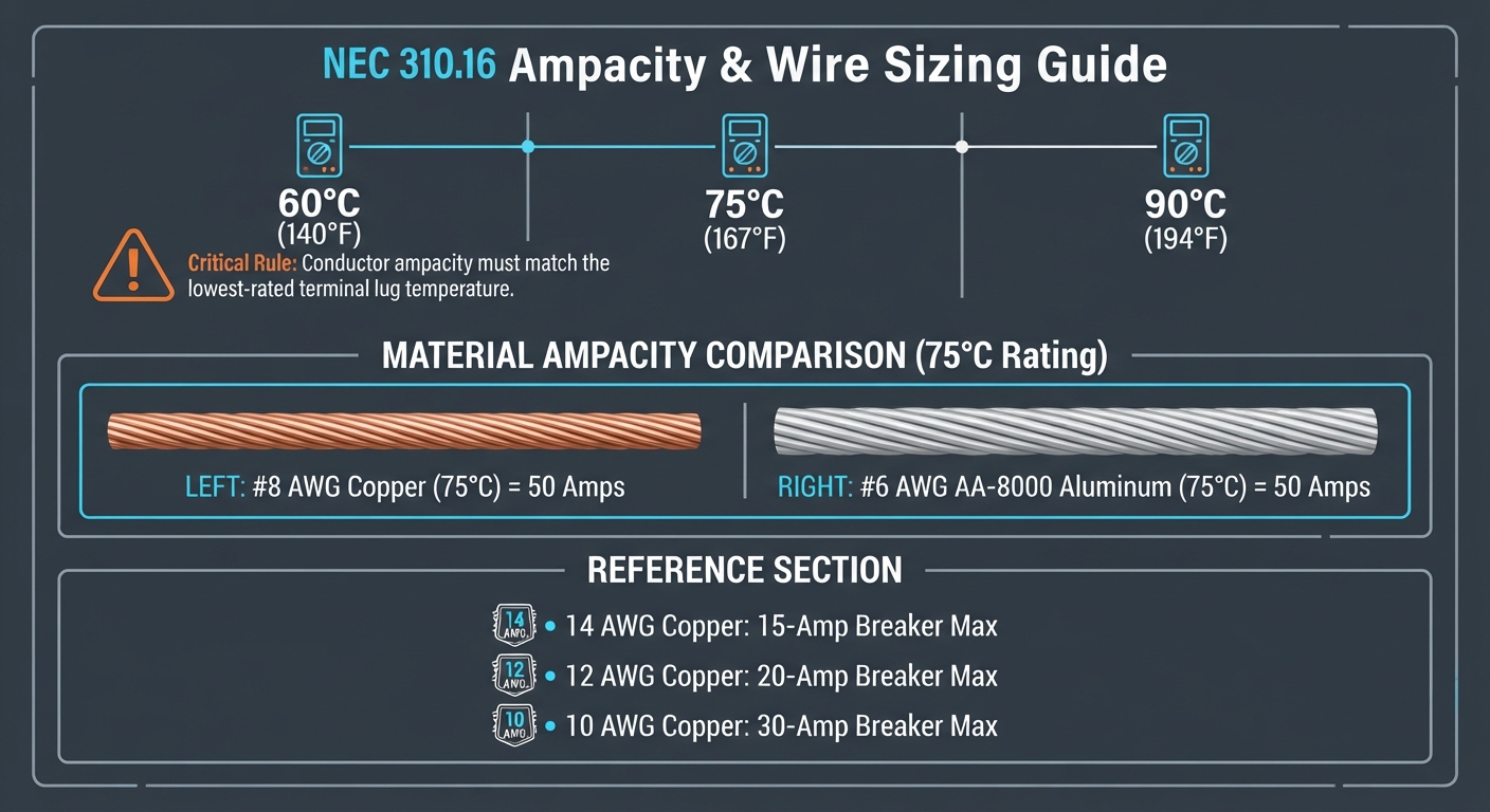
- The Three Temperature Column Paradigm: The standard nec 310.16 table isolates conductor insulation types into three distinct thermal columns: 60°C (140°F), 75°C (167°F), and 90°C (194°F). Even if you deploy a high-end wire rated for 90°C (such as THHN/THWN-2), you must legally size the circuit based on the 60°C column metrics if the terminal lugs on your circuit breaker are only rated for 60°C compatibility, preventing excessive heat migration into the breaker housing.
- The 4-to-6 Current-Carrying Conductor Penalty: When routing multiple branch loops through a single shared conduit pathway or raceway gutter, the ambient heat dispersion factor plunges. Under nec 310 16 guidelines, if a conduit encloses 4 to 6 continuous current-carrying wires, you must apply a mandatory 80% derating multiplier to the baseline ampacity rating, forcing a conductor cross-section adjustment to mitigate cumulative thermal expansion stress.
- Copper vs. AA-8000 Aluminum Volumetric Ratios: Aluminum conductors exhibit higher internal resistivity than pure copper filaments. According to historical data logs within nec 310.15, to safely carry a continuous 50-Amp load, you require a #6 AWG copper conductor wire lines loop, whereas switching to a modern code-compliant AA-8000 series aluminum bundle mandates scaling up to a thicker #4 AWG size to absorb the impedance delta smoothly.
Technical Materials & High-Amperage Ampacity Diagnostic Toolkit
Safely verifying line temperature boundaries and tracking continuous voltage drops requires category-certified metrological instrumentation and insulated hand tools:
| Ampacity Auditing Tool | Primary Engineering Purpose & Trade Safety Rating |
|---|---|
| True RMS CAT IV Clamp Multimeter | Category CAT IV 600V certified to accurately check live line current loads without breaking conductors. |
| Flir Infrared Thermal Imager | Visualizes hidden terminal resistance hot spots across energized panel bus bars. |
| Non-Contact AC Proximity Wand | Proximity sensor calibrated to audibly guarantee 100% disconnect de-energization before wire handling. |
| Calibrated Digital Torque Wrench | Calibration instrument used to torque structural distribution lugs to exact inch-pound specifications. |
| ANSI Z87.1+ Safety Glasses | High-impact polycarbonate lenses protecting eyes from sudden copper arc splatter during panel load tests. |
Conductor Overcurrent Protection Metrics (NEC Table 310.16 / 240.4(D))
To prevent progressive insulation vaporization, systems engineers match structural wire diameters strictly to the maximum overcurrent protective device (OCPD) thresholds enforced under standard code rules:
- 14 AWG Solid Copper Conductor (15-Amp Fuse Ceiling): Regulated strictly under the 310.16 nec 2017 small conductor limitations. Baseline size designed for general residential lighting branches.
- 12 AWG Solid Copper Conductor (20-Amp Breaker Ceiling): The modern infrastructure thickness standard enforced under updated 310.16 nec 2020 mandates for residential appliance sub-circuits.
- 10 AWG Solid Copper Conductor (30-Amp Breaker Ceiling): High-density thickness loop configuration engineered to safely supply continuous loads for water heaters, light commercial machinery, and heavy HVAC air handler packages.
Allowable Ampacities Visual Reference Chart
Technical Phase 2: Ambient Temperature Correction Calculations & Conduit Fill Derating
Executing a flawless, code-compliant wire installation requires going beyond raw chart readings to calculate active thermal derating factors when ambient conditions diverge from standard baseline metrics.
1. Step-by-Step Field Blueprint: Calculating Ambient Correction Penalties
The baseline values listed inside the standard nec 310.16 table are calibrated for an environment ambient temperature of exactly 30°C (86°F). When routing conductors through high-heat areas—such as a structural attic crawl space or an exposed rooftop raceway gutter where solar radiation concentrates heat parameters—you must manually execute this correction trade sequence:
-
Isolate Circuit Potentials: Navigate to your primary panel board distribution center. Disengage the branch circuit breaker switch supplying the conduit loop under review. Attach your safety lockout padlocks and verify an absolute 0V AC parameters state utilizing your non-contact proximity wand before opening wire cavities.
-
Determine the True Ambient Ceiling: Place a digital temperature probe inside the target workspace enclosure during peak heat windows. For this engineering example, let us assume the interior attic ambient temperature spikes up to 45°C (113°F).
-
Extract the Correction Multiplier: Locate the official ambient temperature correction factor table matching your article 310 nec handbook data. For a 90°C insulated THHN copper wire core operating inside a 45°C workspace, the correction coefficient matrix marks a mandatory 0.87 multiplier penalty.
-
Compute the Derated Safe Load Limits: Let us take a #12 AWG THHN wire strand, which features a baseline rating of 30 Amps inside the 90°C column. Apply the structural math equation:
Corrected Ampacity = 30 A × 0.87 = 26.1 Amps
This calculation confirms that while the conductor wire can safely support 30 Amps inside a tempered utility closet, its physical threshold drops down to 26.1 Amps inside the hot attic frame before accounting for breaker terminal limits.
2. Preventing Bundle Meltdowns inside Saturated Raceway Conduits
When multiple conductors are pulled tightly into a single long PVC or EMT metallic run, their fields overlap, creating a thermal choking ring that cooks sheathing layers.
- The Technical Remedy: System integrators strictly enforce the cross-sectional conduit fill weight limits established under Chapter 9 of the code. For over three conductors traversing a single sleeve, the copper area must never occupy more than 40% of the internal conduit volume. Leaving 60% of the pipe open ensures adequate cooling air paths, preventing localized insulation baking faults.
🛠️ The Terminal Lug Compatibility Headroom Note: Look closely at the micro-electronic component blueprints displayed across our modern automated distribution manuals. Notice that while a standard #14 AWG THHN copper wire is rated for 25 Amps within the 90°C column of your nec 310 16 chart, you are legally restricted by the overcurrent guidelines of NEC 240.4(D). This mandate caps the maximum protection device size at 15 Amps for 14 AWG, 20 Amps for 12 AWG, and 30 Amps for 10 AWG, regardless of temperature adjustments. Always prioritize the lowest common structural denominator inside your design layout to prevent inspector redlines.
Troubleshooting Conductor Thermal Overloads & Insulation Decay
- The Breaker Trips Repeatedly During Hot Summer Afternoons Under Normal Load: This specific operational failure confirms an active Ambient Temperature Over-Saturation fault. Your branch conductors were sized based on cold room metrics without applying the mandatory nec 310 15 adjustment multipliers for roof proximity lines. The high ambient heat plus the normal line resistance pushes the breaker’s internal bi-metallic plate past its trip point. Pull a thicker conductor gauge size or re-route the conduit pathway away from solar hot zones to clear the sags.
- The Conductor PVC Insulation Smells Acrid and Shows Discoloration Inside the Panel Box: An absolute indicator of Terminal Screw Arcing caused by a Torque Deficit or Column Mismatch. If an apprentice lands a wire strand onto a breaker lug rated exclusively for 60°C while forcing the wire to carry its maximum 90°C capacity, the terminal connection point transforms into an active heating resistor. De-energize the panel immediately, trim the brittle, charred copper ends, and re-torque all links using a calibrated torque driver to exact factory inch-pound specifications.
- A Multi-Wire Raceway Bundle Explodes or Melts Down Mid-Run: This catastrophic failure confirms severe Conduit Over-Crowding and a missing current-carrying conductor penalty loop. Packing more than 9 uninsulated power strands parallel inside an unventilated raceway sleeve without applying the mandatory 50% derating multiplier causes runaway thermal induction. Replace the entire burned conductor run with fresh THWN-2 lines and split the loads across separate conduits to preserve code integrity.
National Electrical Code Conductor Sizing Regulations
Adhering to strict national structural electrical codes safeguards your home electronics, maintains full property value, and protects your family against hidden arc-fault insulation fire traps. Conductor properties, raceway routing criteria, and ampacity tolerances are heavily cross-regulated under NEC Article 310 (Conductors for General Wiring):
- The Temperature Rating Ceiling Constraint (NEC 310.14): Conductor ampacity ratings shall be determined based strictly on the lowest temperature rating of any connected termination lug, equipment housing terminal, or circuit breaker contact point along the path. You cannot utilize the high-load capacity columns of your nec 310.16 table if your equipment terminal screws are labeled for standard economy limits.
- The Underground Wet Location Requirement (NEC 310.10C): Insulated conductors installed inside underground raceways, direct-burial trenches, or concrete slabs exposed to earth hydration must carry an explicit “W” certification stamped on the insulation jacket (utilizing exclusively THWN-2, XHHW-2, or USE-2 protocols) to prevent water infiltration from rotting the raw copper core.
For the NFPA 70 provisions relevant to this guide on NEC 310.16 Table: Ampacity Ratings & Wire Sizing Manual, consult the Official NFPA 70: National Electrical Code (NEC).
FAQ: Core Code Certification Questions
When a terminal is 60°C rated, conductor ampacity must be taken from the 60°C column of Table 310.16, even if…?
When a terminal is 60°C rated, conductor ampacity must be taken from the 60°C column of Table 310.16, even if the conductor is rated for a higher temperature (such as a 90°C THHN/THWN-2 insulation rating). Under NEC Section 310.14, the circuit’s safe operating capacity is strictly capped by the lowest temperature rating of any connected termination, equipment lug, or circuit breaker contact point along the path.
Conclusion
This guide covers calculating ambient temperature correction multipliers, applying rigid current-carrying conductor derating penalties within saturated conduit runs, and anchoring all wire thickness adjustments to the strict limitations of the nec 310 16 table transforms hazardous DIY projects into highly controlled, electrical milestones. By keeping branch conductor gauges fully aligned with NEC Table 310.16 overcurrent chart ceilings, eliminating dangerous wire grouping practices inside shared raceways, and enforcing separate ground-neutral routing parameters, you build an exceptionally resilient, safe residential power grid. For final checks, complete panel power isolation checks before opening climate cabinets, deploy CAT III certified True RMS multimeters, and complete every terminal adjustment step with safety-first precision.