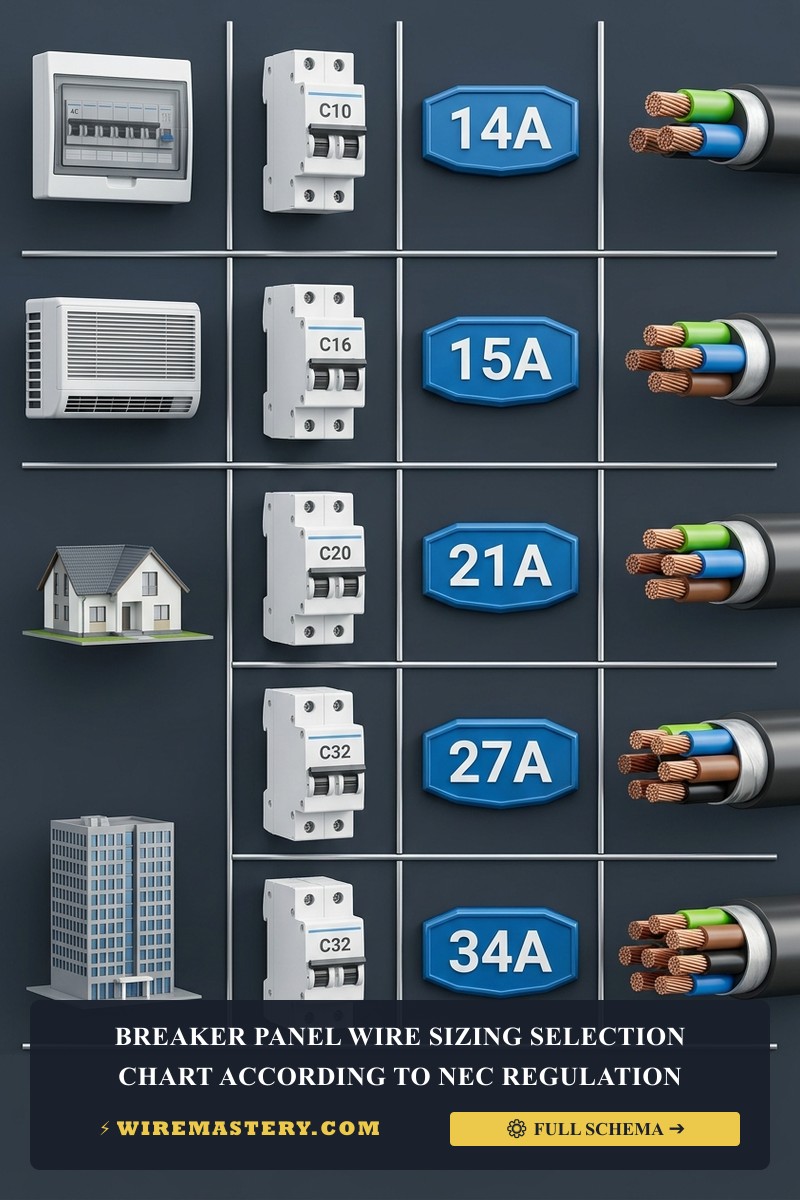
Breaker Panel Wire Sizing: NEC Ampacity & Temperature Codes
Introduction
Engineering a code-compliant, service entrance upgrade or sizing the primary main feeder conductors for a residential breaker panel distribution board demands a rigorous operational command of conductor metallurgy cross-sections, terminal temperature compatibility matrices, and precise thermal correction math. In professional subpanel deployments, selecting a wire gauge cannot depend on generic baseline charts or unaligned amperage listings. Under the strict mandates of the National Electrical Code (NEC), every conductor profile behaves as a thermodynamic element exposed to localized heat build-up inside compressed gutter gutters. Matching a heavy current-carrying line wire to a circuit breaker lug terminal without evaluating whether the hardware is rated for 60°C, 75°C, or 90°C continuous thermal thresholds violates insurance compliance metrics and creates an immediate fire hazard behind enclosure deadfront plates.
To prevent progressive insulation jacket decay across high-density automated properties, installers must anchor these feeder sizing variables directly to verified NEC Article 220 residential load calculation equations and certified electrical contractor contract closeout engineering protocols.
This trade manual despatches the fundamental processes required to interpret NEC Table 310.16 temperature constraints, calculate precise mathematical adjustment deratings for bundled raceways, and deploy professional on-site diagnostic toolkits.
Core Panel Board Wire Sizing Parameters
Before feeding heavy service entrance conductors into vertical conduit tracks or torque-locking main lugs, decode these essential code boundaries:
- The Terminal Temperature Constraint (NEC 110.14(C)): Conductor ampacity sizing must be calculated based on the temperature rating of the lowest-rated element along the circuit loop, including the device lug terminal plates. Even if you install a high-performance wire wrapped in a 90°C rated insulation jacket (such as THHN stranded copper), if the circuit breaker terminal pressure plate is stamped exclusively for 75°C or 60°C entries, you are legally forced to size your wire capacity based on the lower temperature column, neutralizing the extra insulation headroom.
- The NM-B Romex 60°C Sizing Floor: Under strict residential construction regulations, non-metallic sheathed cable types (NM-B Romex) are legally restricted to the 60°C ampacity column for finalizing circuit limits, regardless of multi-conductor layout additions. The 90°C column parameters can be utilized exclusively as a mathematical baseline from which to apply adjustment deratings for ambient heat or bundled stud holes.
- The 310.12 Residential Service Waiver Ceiling: For single-phase dwelling services rated 100 Amps through 200 Amps, the code permits deploying a specialized service entrance sizing waiver, allowing main feeder conductors to be scaled down to carry a capacity equal to 83% of the main overcurrent protective device rating, significantly reducing copper materials costs.
Technical Materials & High-Energy Gutter Sizing Toolkit Reference
Safely opening energized panel board enclosures and measuring micro-ampere conductor resistance variables requires specialized testing instrumentation and ASTM-certified insulated tools:
| Industrial Sizing Tool | Primary Engineering Purpose & Trade Safety Threshold |
|---|---|
| True RMS CAT IV Clamp Meter | Category CAT IV 600V certified to safely capture continuous phase current loading spikes. |
| 1000V Insulated Torque Wrench | Precision instrument to torque main service lug screws to exact manufacturer inch-pound specs. |
| Infrared Thermal Laser Scanner | Maps active thermal hotspots across breaker casings from a safe distance before disassembly. |
| Dual-Phase Non-Contact Tester | High-sensitivity sensor calibrated to verify absolute circuit de-energization before wire handling. |
| Class 00 Dielectric Rubber Gloves | Certified high-density rubber wraps rated to block up to 500V AC continuous contact tracks. |
Conductor Sizing Chart: The Definitive NEC Table 310.16 Master Index
To draft a professional line-item estimate that satisfies structural city building inspectors, field crews track the exact thermal columns defined under NEC Article 310.16 parameters:
High-Capacity Copper vs. Aluminum Terminal Sizing Grid
| Wire Size Gauge (AWG / kcmil) | 60°C Column (Amps) | 75°C Column (Amps) | 90°C Column (Amps) | Core Trade Application & Material Blueprint |
|---|---|---|---|---|
| 14 AWG Copper | 15 | 15 | 20 | Standard residential lighting and bedroom general convenience branches. |
| 12 AWG Copper | 20 | 20 | 25 | Kitchen Small Appliance Branch Circuits (SABC) and bathroom vanity plugs. |
| 10 AWG Copper | 30 | 30 | 40 | Dedicated continuous loads including electric clothes dryers and water heaters. |
| 6 AWG Copper | 55 | 65 | 75 | Standard subpanel feeder lines and high-output 240V electric range loops. |
| 2/0 AWG Copper | 115 | 145 | 175 | Code-compliant copper conductor baseline to supply a 200-Amp master subpanel center. |
| 4/0 AWG Aluminum | 120 | 150 | 180 | Industry standard aluminum service line to deploy a 200A residential entrance drop. |
Technical Phase 2: Mastering Derating Equations & Main Lug Terminations
To execute a flawless, code-compliant breaker panel wire configuration, a field engineer must look past raw table indexes and apply real-world mathematical correction factors matching the physical installation environment.
1. The Real-World Engineering Math of Conductor Derating (NEC 310.15)
Failing to apply precise correction adjustments leads to severe thermal build-up inside compressed conduits, melting the wire jackets from the inside out.
-
Ambient Temperature Correction Adjustment (Ft): When routing branch lines or subpanel feeders through high-heat environments (such as an attic cavity or an unshaded exterior rooftop conduit track where temperatures exceed 86°F / 30°C), you must multiply the wire’s baseline ampacity by the precise decimal factor extracted from NEC Table 310.15(B)(1). For example, a THHN wire operating in 115°F ambient air carries a correction multiplier of 0.82.
-
Conductor Bundling Adjustment (Fa): Under the strict mandates of NEC 310.15(C)(1), when more than three current-carrying conductors are bundled tight or routed through the same conduit track for a continuous length exceeding 24 inches, the wire’s ampacity must be slashed to prevent inductive heat traps.
Adjusted Conductor Ampacity = Table Baseline Ampacity (90°C) × Ft × Fa
The Sizing Protocol: To calculate an adjusted line safely, always launch the multiplication using the wire’s 90°C insulation baseline capacity. Provided the final calculated adjusted ampacity number remains equal to or higher than the primary circuit breaker’s 75°C protection limit, the installation is legally cleared and safe to operate under continuous continuous loads.
2. Step-by-Step Field Blueprint: Terminating Main Panel Service Lugs
Once your adjusted conductor profiles satisfy overcurrent protective ceilings, apply this systematic field installation sequence to execute the connection:
- Isolate Primary Utility Drops: Contact your municipal power provider to pull the outdoor meter plug entirely. Verify an absolute 0V AC state across both main incoming service legs using your CAT IV clamp meter before handling raw copper.
- Jacket Scoring and Anti-Oxidant Packing: Strip exactly 1 inch of insulation off your 2/0 copper or 4/0 aluminum lines using a hook blade utility knife. Critical Requirement: If deploying aluminum conductors, immediately wire-brush the exposed strands to break through the oxide skin and pack the wire threads with a certified zinc-based anti-oxidant joint compound to block galvanic corrosion.
- Applying Calibrated Torque Controls (NEC 110.14(D)): Insert the prepared wire shanks deep into the primary pressure-plate main lugs at the top of the breaker panel center. Take your 1000V insulated torque wrench and tighten the lug screws to the exact manufacturer engineering specs stamped on the panel chassis (typically 250 inch-pounds for a 200A main service). This precise torque prevents the metal from cold-flowing or slipping loose during seasonal expansion and contracting cycles.
🛠️ The Plug-On Neutral Gutter Balance Note: Look closely at the multi-circuit panel board blueprints displayed across our modern home automation manuals. Modern high-end panels utilize an integrated Plug-On Neutral bus bar assembly. Unlike legacy distributions where every individual Arc-Fault (AFCI) circuit breaker required a long, flexible white curly pigtail wire routed manually back to the neutral bar, plug-on neutral breakers clamp directly onto an integrated metal rail track. This engineering feature eliminates 80% of wire congestion inside the panel gutters, maximizing ventilation headroom and suppressing wire pinching fault codes during high-density wire expansions.
Troubleshooting Panel Board Thermal Failures & Wiring Anomalies
- The Main Service Lugs Emit a Sizzling Sound and Register Over 145°F Under Infared Sweeps: This catastrophic behavior indicates an active aluminum conductor cold-flow loosening or an anti-oxidant omission fault. If the installer tightened the heavy service entrance lines using manual tools by “feel,” the aluminum wires will cold-flow out from under the pressure plate. The loose connection multiplies terminal resistance, converting continuous current into a severe fire hazard. Isolate the outdoor meter drop immediately and torque the main lugs down to specifications.
- The Newly Reset AFCI Breakers Trip Intermittently Upon Panel Initialization: An absolute indicator of an active downstream neutral-to-ground wire pinch executed during the downstream branch re-packing phase. While legacy panels with old thermal breakers were completely blind to micro-ampere leakage paths, a modern Arc-Fault (AFCI) or GFCI breaker uses internal solid-state current transformers to monitor line balances. If a white neutral wire touches a bare ground wire inside a tight gang box, the breaker drops the line offline instantly. Run unpowered resistance continuity tests to isolate the short circuit box by box.
- The Subpanel Bus Bars Corrosion Mats Flaking After Wet Seasons: This indicates an active conduit water migration track. If an installer routes an exterior service conduit into the top of an indoor panel board without installing a certified NEMA NEMA weather-proof hub or an approved continuous duct-seal putty plug, outdoor condensation will drain straight down the inner pipe jacket. This fluid path pits the copper bus rails, generating carbon tracking shorts. Install an intermediate exterior drain loop to divert moisture paths entirely.
National Electrical Code Wire Sizing & Panel Board Regulations
Adhering to strict national structural regulations protects your home infrastructure from electrical fire hazards, maintains full property insurance validity, and ensures complete alignment with federal inspection safety boundaries. Panel board wire installations are heavily regulated under NEC Article 310 (Conductors for General Wiring) and Article 408 (Switchboards and Panelboards):
- The Panel Directory Labeling Mandate (NEC 408.4): Every circuit breaker and overcurrent protection handle positioned inside a residential distribution center must be clearly, permanently, and legibly labeled with its explicit room layout branch designation. Utilizing vague handwritten scratch notes or leaving the directory completely blank is a critical code compliance failure.
- Enclosure Gutter Spatial Clearances (NEC 312.6): Conductor wires entering a breaker panel box must maintain minimum wire-bending workspace depths to prevent structural stress on the terminal lug joints. Forcing high-capacity #6 AWG through 500 kcmil feeder conductor bundles around tight sheet-metal radius walls without proper gutter headroom violates federal safety inspection metrics.
For the NFPA 70 provisions relevant to this guide on Breaker Panel Wire Sizing: NEC Ampacity & Temperature Codes, consult the Official NFPA 70: National Electrical Code (NEC).
Conclusion
This guide covers executing precise mathematical derating adjustments under NEC Article 310.15 guidelines, interpreting Table 310.16 terminal temperature column thresholds, and executing high-amperage main service lug terminations using calibrated torque wrenches transforms complex breaker panel wire sizing into a highly controlled science. By keeping conductor cross-sections fully aligned with overcurrent protection boundaries, enforcing separate ground-neutral bus insulation paths inside downstream subpanel enclosures, and respecting mandatory NEC workspace spatial envelopes, you build an exceptionally resilient, safe home grid infrastructure. For final checks, complete utility energy isolation safety checks before raw line handling, deploy CAT IV certified digital clamp ammeters, and execute every high-voltage terminal calibration milestone with safety-first precision.







