Samsung and Whirlpool Refrigerator Ice Maker
Executing a reliable, long-term repair on a malfunctioning built-in automatic ice maker unit inside premium residential French-door or side-by-side refrigerators requires a technical diagnostic protocol that addresses mechanical refrigeration, low-voltage control circuits, and localized water-delivery thermodynamics. Modern automatic ice makers developed by major manufacturers like Samsung and Whirlpool operate as automated electro-mechanical sub-systems. These components utilize solid-state micro-switches, infrared beam sensors, and dedicated low-voltage heating elements to harvest ice cubes systematically. However, when these assemblies experience structural failures—such as compartment air infiltration or infrared optical grid misalignment—they do more than stop producing ice. A jammed ejector arm or a continuously energized water inlet solenoid can cause localized freezing blockages or continuous sub-freezing water leaks. For home automation systems tracking appliance power metrics, ensuring your refrigeration lines tie into code-compliant residential service panel and branch wire layouts safeguards logic boards against voltage dropouts.
The distinct hardware architectures of Samsung and Whirlpool ice makers, the physical remediation of frozen ice compartments, and step-by-step low-voltage component testing workflows.
Core Hardware Diagnostic Parameters
Before unmounting factory mold assemblies or handling internal low-voltage wire harnesses, decode these operational parameters:
-
The Ice Room Temperature Baseline: For an automatic ice maker module to initialize its internal harvesting cycle, the localized compartment temperature sensor (thermistor) must read and sustain a baseline temperature at or below 8°F (-13.3°C). If the ambient air inside the ice room floats above this threshold, the control board will lock out the harvesting motor indefinitely.
-
The Water Inlet Solenoid Timing: Refrigerator water valves do not calculate volume using flow meters; instead, the primary control board sends a 120V AC signal for a precise duration (typically 4.5 to 7.0 seconds) to open the valve diaphragm. If water pressure falls below 20 PSI, the mold will underfill, creating malformed or hollow ice cubes.
-
The Ground Leakage Constraint: Because these components operate at the intersection of continuous water pathways and line-voltage components, any insulation breakdown inside the mold heater element will bleed micro-currents to the chassis, triggering sensitive AFCI/GFCI breakers.
Technical Materials & Appliance Diagnostic Toolkit Checklist
Safely clearing ice over-growth and auditing low-voltage infrared emitter boards requires specific diagnostic instrumentation and specialized trade tools:
| Appliance Repair Tool | Primary Engineering Purpose & Trade Application |
|---|---|
| True RMS Digital Multimeter | Category CAT III 600V certified to audit solenoid resistances and test thermistor DC voltage drops. |
| Food-Grade RTV Silicone Sealant | High-density waterproof silicone required to seal raw cabinet cracks and block warm air leaks. |
| Variable-Temperature Heat Gun | Used to safely melt internal ice blockages inside plastic linings without warping components. |
| Infrared Laser Thermometer | Measures absolute, non-contact internal ice room surface temperatures before forcing harvesting cycles. |
| Insulated Nut Driver Set | Securely backs out grounded 1/4-inch hex screws anchoring the ice maker housing structure. |
Sizing Branch Circuits & Appliance Current Loads (NEC Article 422)
To maintain absolute system safety and prevent progressive voltage drops that cause kitchen lights to flicker when the refrigerator compressor cycles on, you must ensure your refrigeration infrastructure aligns with NEC Article 422 continuous loading limits:
- Dedicated 15-Amp or 20-Amp Circuit (NEC 422.16): Standard residential refrigerators equipped with automatic high-wattage defrost heaters and ice harvesting assemblies must be supplied by an individual, dedicated branch circuit. This line should utilize a minimum of #14 AWG or #12 AWG solid copper conductors enclosed within a code-compliant white or yellow Romex jacket, isolated entirely from kitchen small appliance circuits (SABC).
- Grounding and Cord Protection: The appliance cord must incorporate an unbroken, factory-molded grounding prong. Utilizing extension cords or ungrounded adapters to supply a refrigerator ice maker system is an extreme code violation that creates a direct shock hazard.
Deep Diagnostics: Solving the Samsung “Ice Room Freeze-Up” Phenomenon
The single most frequent failure mode encountered on modern Samsung French-door refrigerators is the progressive freezing and jamming of the entire ice maker assembly.
The Root Cause: Warm Air Infiltration
Unlike traditional layouts where the ice maker sits inside a naturally sub-freezing freezer drawer, French-door models locate the ice maker assembly inside an insulated cabinet box housed within the 38°F fresh food refrigerator cavity.
- Over operational cycles, the factory foam seals surrounding the cabinet margins or the ice discharge chute flap begin to settle, creating micro-gaps.
- Warm, moist ambient room air from the kitchen is drawn into the low-pressure ice room compartment through these gaps.
- The moisture in the warm air condenses instantly upon hitting the sub-zero evaporator loop, creating massive frost and ice over-growth. This ice physically encases the harvesting ejector arm, jams the drive gears, and blocks the fill tube.
The Technical Remediation Protocol
To permanently fix a frozen Samsung ice room box, simple software resets are useless. Apply this comprehensive field overhaul sequence:
- Isolate Power & Forced Defrost: Unplug the main appliance cord from the wall enclosure. Use your variable-temperature heat gun on a low, controlled setting to slowly melt the ice blockages encasing the plastic module assembly. Never use screwdrivers or sharp ice picks to chip at the ice, as you will instantly puncture the aluminum evaporator lines, causing terminal freon leaks.
- Extracting the Module: Back out the retaining screws and drop the ice maker assembly down to un-clip the low-voltage wire loom harness. Dry the entire plastic cabinet cavity using an absorbent microfiber towel until no moisture remains.
- Sealing the Infiltration Paths: Take a tube of premium food-grade RTV silicone sealant. Run a continuous, heavy bead of silicone along the hidden seam where the ice room wall meets the refrigerator liner shell. Apply silicone around the structural wire harness entry grommet and inspect the ice chute sealing flap for complete mechanical compression. This absolute seal stops warm air drafts from entering the box, permanently solving the ice accumulation loop.
Deep Diagnostics: Solving Whirlpool Infrared Optical Grid Faults
Unlike traditional mechanical bail arms that drop down to gauge ice levels, modern Whirlpool ice maker architectures deploy an advanced Infrared Optics Sensor Grid to monitor ice bin capacity.
The Infrared Beam Mechanics
The assembly features an emitter board on the right wall of the freezer liner and a receiver board on the left wall. These boards project a continuous, invisible infrared light beam directly across the ice bin cavity.
- Bin Full State: When the ice level rises high enough to physically block the infrared beam path for a continuous 5 minutes, the receiver module toggles its signal output, cutting power to the harvesting motor to prevent an ice overflow event.
- The Component Failure: Over extensive thermal cycles, the plastic diagnostic lens covers over the infrared diodes can become scratched, clouded with mineral film, or frost-coated, causing the beam to scatter. The receiver interprets a scattered beam as a “Bin Full” state, stopping all ice production even when the bin is completely empty.
The Optical Support Audit Protocol
To bypass software logic and verify if your Whirlpool optical board array is defective, execute this structured trade sequence:
- Open the freezer door panel and locate the diagnostic LED indicator light mounted on the emitter board trim face.
- Analyze the Blink Codes:
- Two Blinks followed by a Pause: Indicates the infrared beam is blocked or the boards are misaligned. Clean the lenses using isopropyl alcohol and ensure the doors are square.
- Solid Steady Light: Indicates the optical path is completely clear and aligned, confirming the boards are functioning.
- If the LED stays completely dark while the refrigerator draws line power, use your digital multimeter to check voltage across the main power leads on the board wiring harness. If the meter registers +12V DC but the LED fails to illuminate, the internal logic chip is fried and requires a new board assembly.
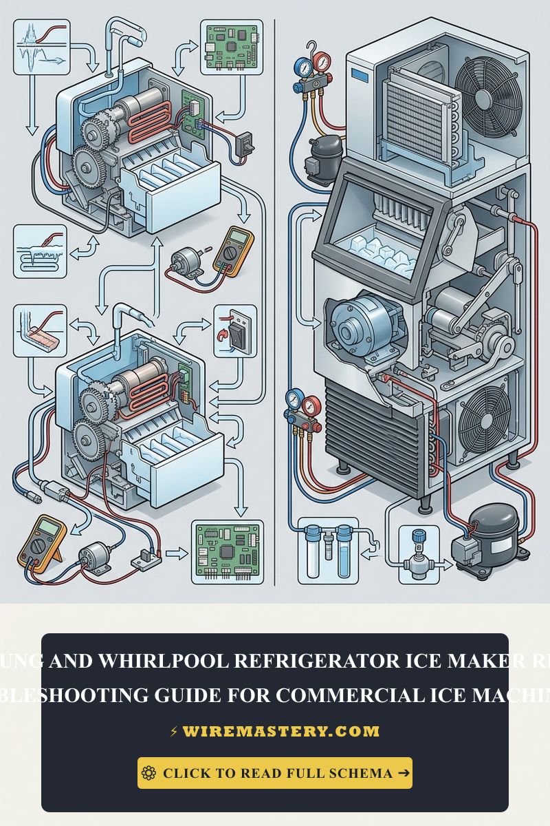
🛠️ Solenoid Inductive Surge Note: Look closely at the dual-valve water assemblies showcased across our technical component portfolios. Notice that water inlet valves deploy fine wire coils to create an electromagnetic field that pulls open the internal rubber water seal. When these solenoids disconnect or cycle off rapidly, they generate a high-voltage inductive kickback spike. Always ensure your main controller boards feature integrated transient voltage suppression TVS diode protection circuits to clamp these spikes before they fry sensitive appliance microprocessors.
Technical Phase: Executing an Electrical Component Multimeter Audit
If your ice room cabinet is completely clear of frost and air leaks but refuses to cycle, use your digital multimeter to perform a live and unpowered diagnostic sequence on the core mechanical parts:
1. The Water Inlet Valve Ohmmeter Check (Unpowered Test)
- Unplug the main refrigerator power cord from the wall outlet enclosure to isolate line potential.
- Access the lower rear machinery compartment and locate the primary water inlet valve solenoid terminals.
- Disconnect the wire slip-on terminals from the valve coils. Rotate your multimeter dial to Resistance mode (Ohms).
- Place your testing probes onto the two metal terminals of the ice maker valve solenoid coil:
- A Healthy Solenoid: The meter must display a resistance reading floating between 200 Ω and 500 Ω.
- A Defective Coil: If the meter registers an infinite open-loop message (O.L.) or reads close to 0 Ω, the internal copper wire windings are severed or shorted. The valve is defective and will never open, demanding immediate replacement.
2. The Thermistor Voltage Drop Sweep (Live Test)
- Re-engage power to the appliance. Set your multi-tester dial to DC Voltage mode (V_avg).
- Locate the low-voltage sensor harness leading into the ice maker mold body. Connect your probes across the C (Common) and Signal leads.
- At room temperature (77°F / 25°C), the thermistor should drop approximately 2.5V DC based on a standard 10kΩ resistance curve. If the ice room is verified at 0°F via your laser thermometer but the voltage registers a flat 5V or 0V, the sensor has suffered an internal breakdown, blinding the control board to the compartment’s true thermal state.
Step-by-Step Ice Maker System Reset & Commissioning Manual
If you have completed mechanical alignments or replaced a component, execute a hard system restart to cycle the hardware matrix:
- Locate the Physical Reset Switch: On modern Samsung assemblies, look for a small, rectangular soft-rubber push-button hidden along the front or bottom face of the clear plastic ice maker casing frame. On Whirlpool modular assemblies, pop off the front plastic shroud to expose the integrated gear assembly drive wheels.
- Forcing the Harvest Cycle: Press and hold the reset button continuously for exactly 10 seconds. For Whirlpool mechanical wheels, use an insulated jumper wire to bridge the “T” and “H” holes on the module face for 2 seconds.
- Monitor the Mechanical Sequence: The unit will emit an audible chime or click, initializing an emergency test cycle. The internal motor will slowly rotate the ejector arms 360° to dump dummy cubes, trigger the mold heating element for 30 seconds, and open the water inlet valve for 5 seconds to fill the tray. Maintain clear spatial clearance during rotation to avoid breaking the gear tracks.
National Electrical Code Appliance Compliance Standards
Adhering to strict national structural regulations protects your home electronics from damage and ensures full property insurance compliance. The National Electrical Code strictly regulates residential large appliances and motorized equipment under NEC Article 422 (Appliances):
- Grounding Continuity Rules (NEC 422.15): Refrigerator chassis frames house a complex mix of water lines, copper capillary tubes, and high-amperage compressor assemblies. The code mandates that all exposed non-current-carrying metal parts must maintain an absolute, low-impedance grounding path back to the main utility panel ground bar to prevent severe shock hazards during an insulation blowout.
- Circuit Cord Accessibility (NEC 422.16): The appliance attachment plug must serve as the primary legal means of electrical disconnection. The wall receptacle enclosure must be positioned to allow un-obstructed physical access, preventing scenarios where technicians are forced to handle live copper components inside cramped wall channels during an active short-circuit event.
For the NFPA 70 provisions relevant to this guide on Samsung & Whirlpool Refrigerator Ice Maker Repair Guide, consult the Official NFPA 70: National Electrical Code (NEC).
Conclusion
This article explains refrigerator ice maker operation principles, clearing warm air infiltration leaks inside Samsung ice rooms with food-grade RTV silicone, and auditing Whirlpool infrared optical grid boards using precise multimeter resistance sweeps transforms complex appliance faults into systematic solutions. By enforcing dedicated branch circuit line boundaries, realigning crossed low-voltage wire looms, and respecting mandatory NEC grounding rules, you construct an extremely resilient residential technology framework. For final checks, complete appliance power isolation before checking live terminals, utilize CAT III certified diagnostic instruments, and maintain code-compliant care across every component step.