How to Wire a Switch and Outlet Combo: Step-by-Step Guide
Introduction
Integrating a dedicated switch loop into a standard residential electrical receptacle circuit is an exceptional layout upgrade that enhances spatial utility and introduces adaptive lighting controls across bedrooms, home office zones, and living room nodes. Within residential construction conventions, this configuration traditionally executes in two distinct formats: a single device housing a combined switch-and-receptacle mechanism (Combo Switch/Outlet) or a standalone wall switch that dictates power delivery to a remote wall receptacle. For properties deploying advanced automation frameworks, wiring these junctions correctly establishes the primary power grid required to interface with modern smart lock installation wiring loops and automated utility layers.
The mechanical blueprints for wiring half-switched and fully switched outlets, terminal identification matrices, and National Electrical Code (NEC) load boundaries.
Core Circuit Engineering Thresholds
Before unmounting factory terminal links or feeding multi-conductor cable lines into plastic gang box enclosures, decode these structural baselines:
- The Half-Switched Outlet Paradigm: A professional installation frequently requires splitting a duplex receptacle. This architecture enables the top outlet slot to toggle with a wall switch (for a localized floor lamp) while the bottom outlet slot maintains an un-switched, continuous 120V line feed to power clocks or phone charging blocks.
- The Connecting Tab Break Requirement: To split a standard duplex receptacle, a field technician must physically remove the small metal break-away brass tab linking the two positive brass screw terminals. Failing to break this tab before supplying switched and un-switched hots onto the side screws will create a parallel bridge, rendering the switch loop completely useless and leaving both outlets hot continuously.
- Neutral Commonality Restrictions: While the hot phase side can split independently, both the top and bottom receptacle slots share a single, unbroken neutral connection strip on the silver terminal side of the device yoke.
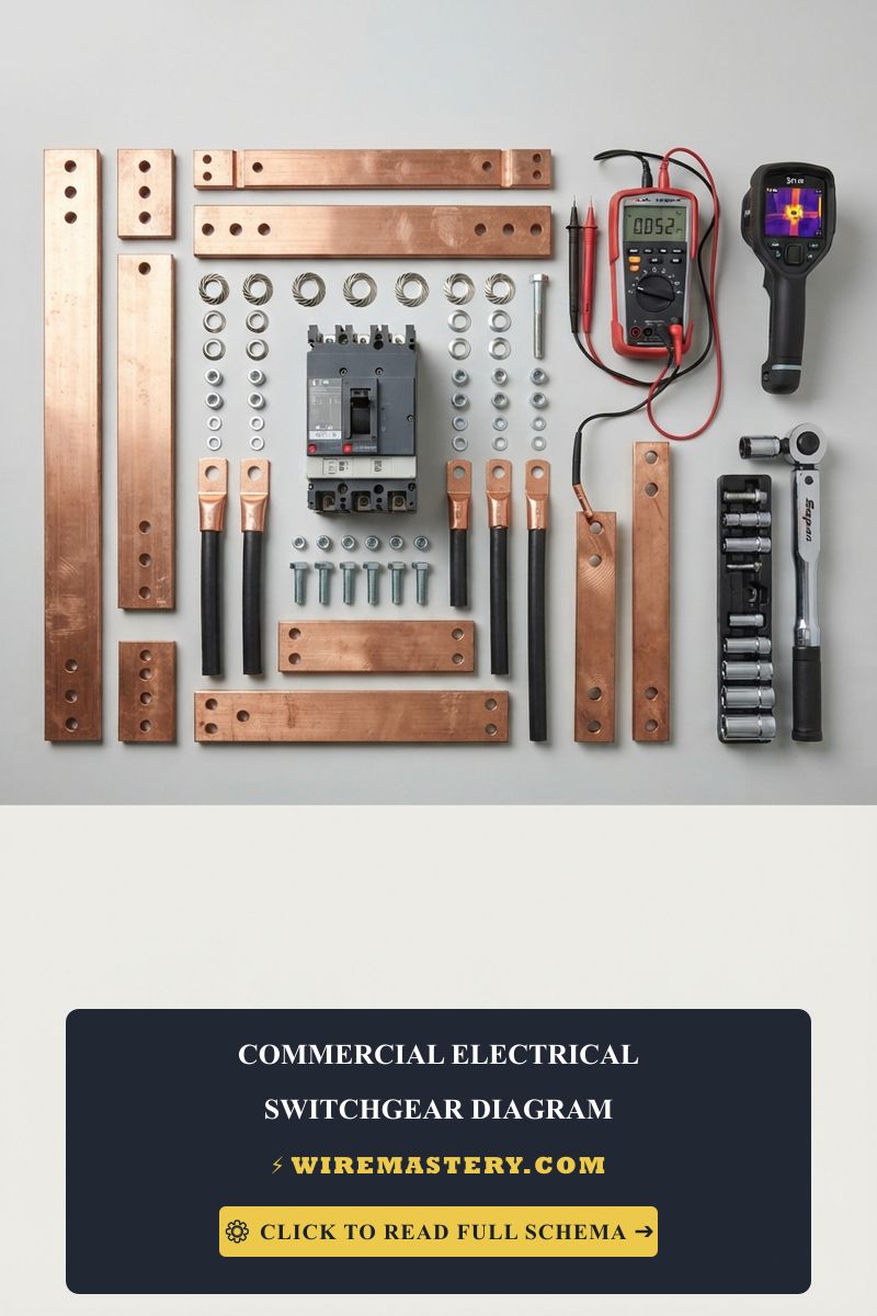
Technical Materials & Device Commissioning Toolkit Checklist
Executing clean, code-compliant device installations and diagnosing live circuit continuity demands specific trade equipment and insulated hand tools:
| Electrical Installation Tool | Primary Technical Purpose & Application |
|---|---|
| Digital Auto-Ranging Multimeter | Measures clean AC voltage line potentials (0V to 130V) across side terminal screws. |
| Non-Contact AC Voltage Tester | Monitors the perimeter of the box enclosure to guarantee a 100% de-energized workspace. |
| Ratcheting Solid Wire Strippers | Calibrated to shear outer PVC protective casings cleanly off #14 AWG and #12 AWG copper lines. |
| Heavy-Duty Needle-Nose Pliers | Formulates precise clockwise loops to wrap around terminal shanks and breaks away brass linking tabs. |
| GFCI / Receptacle Pocket Tester | Plugs directly into the finished slots to instantly audit for open neutral or reversed polarity faults. |
Sizing Conductor Gauges & Ampacity Tables (NEC Article 310.16)
Selecting an incorrect conductor thickness introduces dangerous electrical resistance, leading to progressive insulation decay inside wall cavities long before the circuit breaker can trip. The National Electrical Code strictly regulates branch circuit conductor cross-sections based on nominal overcurrent protection limits:
- 14 AWG Solid Copper Conductor (White Romex Jacket): Rated strictly for 15-Amp branch circuits. Used primarily for standard residential lighting runs and low-draw general-use outlet loops.
- 12 AWG Solid Copper Conductor (Yellow Romex Jacket): Rated strictly for 20-Amp branch circuits. Mandatory for kitchen small appliance branch circuits (SABC), bathroom nodes, and high-density office zones.
Decoding the Duplex Receptacle Screw Terminal Matrix
To read a wire outlet with switch installation manual schematic with complete clarity, you must ignore generic wire colors and trace functions by matching terminal metals to their specific circuit roles:
Standard Split-Duplex Hardware Identification Mapping
| Terminal Pin Designation | Terminal Screw Metal / Color | Source Conductor Link | Core Engineering Role |
|---|---|---|---|
| Line Hot (Continuous) | Brass / Yellow Gold | Black Conductor Core | Delivers un-switched 120V power to the bottom outlet slot. |
| Switch Hot (Controlled) | Brass / Yellow Gold | Red Conductor Core | Delivers toggled 120V power from the switch to the top slot. |
| Grounded Neutral | Silver / Bright Chrome | White Conductor Core | Completes the 120V electrical path back to the panel return bus. |
| Equipment Ground | Hex Head / Bright Green | Bare Copper Core | Redirects internal chassis leakage currents safely to the earth. |
Step-by-Step Installation Blueprints: Splitting a Duplex Receptacle
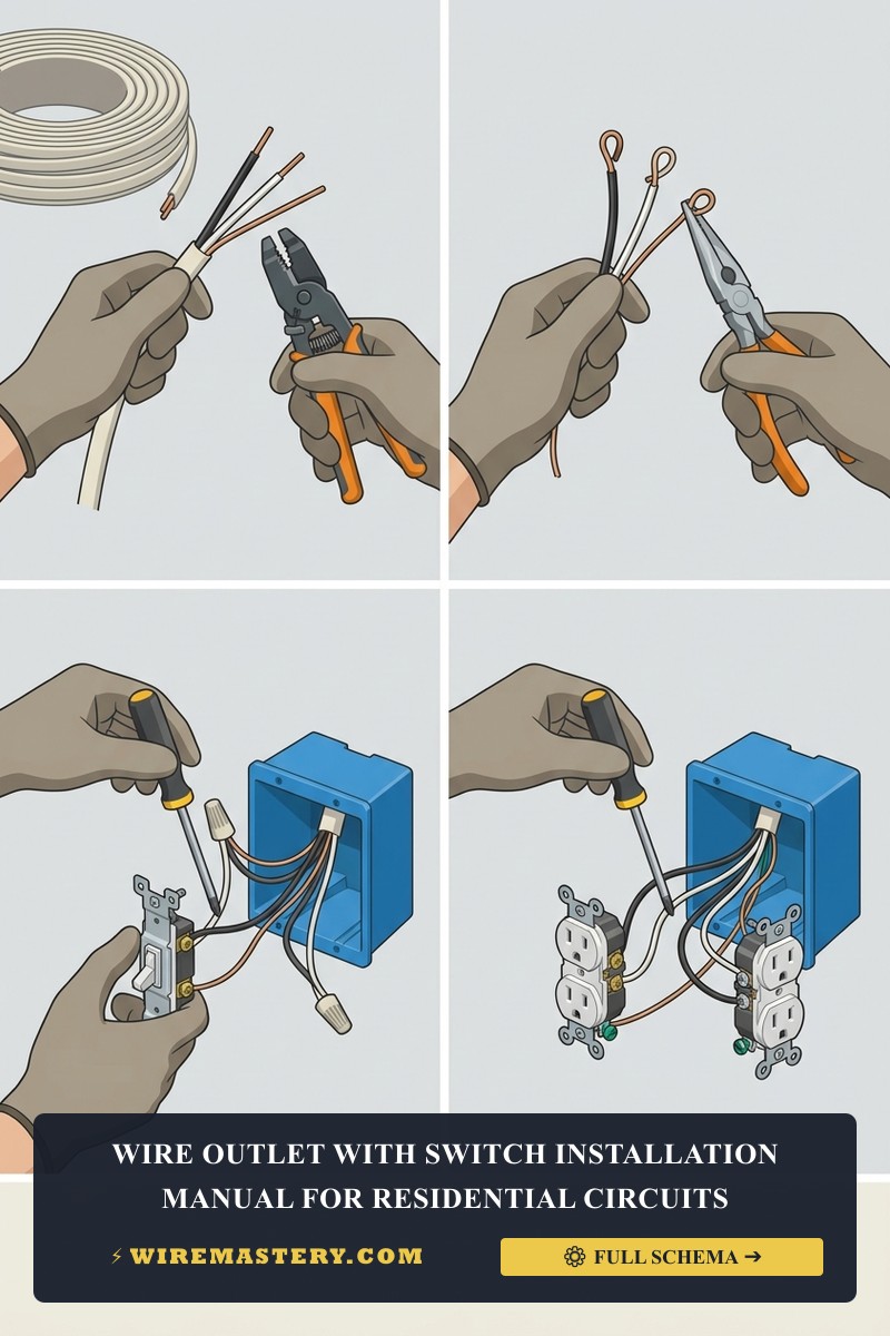
To configure a professional half-switched layout where a standalone wall switch dictates power exclusively to the top slot of a remote outlet, apply this systematic field installation sequence:
1. Pre-Installation Isolation Protocol
Locate your property’s primary breaker panel block. Identify and disengage the circuit breaker supplying power to the workspace area. Remove the decorative faceplates at both wall locations. Prior to backing out any hardware, press your non-contact voltage tester against all terminal screws to confirm a complete 0V AC state.
2. Breaking the Connecting Brass Tab
Take your new duplex receptacle. Locate the two brass (gold) terminal screws on the hot side of the device yoke. Grip the small metal break-away brass tab linking these two screws together firmly using the tip of your needle-nose pliers. Bend the tab back and forth aggressively until the metal snaps off. Leave the silver-side terminal tab completely intact to preserve a common neutral return path for both slots.
3. Wiring Box 1: The Standalone Wall Switch Box
Box 1 receives the primary 12/2 or 14/2 feed from the panel board and routes a 12/3 or 14/3 traveler bundle down to the outlet enclosure.
- Connect the incoming Black panel line hot wire directly to the bottom brass screw terminal of the single-pole switch.
- Connect the incoming White panel neutral wire directly to the outgoing white neutral wire running to the outlet box using a UL-listed wire nut. Do not hook it to the switch.
- Take the outgoing multi-conductor cable running to the outlet box: connect its Black wire (Un-switched Hot) to the bottom switch terminal alongside the panel feed (or use a pigtail bridge), and connect its Red wire (Switched Hot) directly to the top brass screw terminal of the switch.
4. Wiring Box 2: The Split Receptacle Outlet Box
- Connect the incoming White neutral wire directly to either of the two silver terminal screws on the neutral side of the receptacle.
- Connect the incoming Black wire (Continuous 120V) directly to the bottom brass screw terminal. This powers the lower slot continuously.
- Connect the incoming Red wire (Switched 120V) directly to the top brass screw terminal. This routes toggled power to the upper slot.
- Form clean clockwise loops with your bare copper safety ground conductors, bond them to the green grounding hex screws in both boxes, and secure the yokes flush into the wall tracks.
🛠️ Combo Device Alternative Routing: Look closely at the hardware designs displayed throughout our smart home optimization portfolios. If you are deploying an integrated Combo Switch/Outlet mechanism inside a tight single-gang enclosure, you must navigate a different configuration. If the brass tab on a combo unit is left intact, the switch will dictate power directly to its own integrated outlet slot. For advanced automated applications requiring full dimming capabilities, ensure you cross-reference your layout with our complete guide on wiring a dimmer switch on a 3-way circuit to isolate signal lines cleanly.
Troubleshooting Common Outlet Loop Failures
- Both Outlet Slots Toggle with the Switch: This is the absolute signature symptom of an installer forgetting to break the connecting brass tab on the hot side of the receptacle. The switched red line and continuous black line are tied together in parallel across the intact metal link, forcing the entire device to override switch logic. Disengage the breaker, pull the device, and snap the tab off completely.
- The Switch Trips the Circuit Breaker Instantly When Flipped ON: This indicate a catastrophic dead short circuit. It typically happens when an amateur installer attempts to wire the white neutral wire directly onto one of the side screws of a standard single-pole switch. A switch has no neutral terminal; it only slices the hot phase. Connecting a hot and neutral together on a single-pole switch creates a direct short across the contact points, triggering a blinding arc-flash inside the box.
- Appliances Plugged Into the Bottom Slot Drop Out Under Load: Check for poor terminal screw torque or utilization of loose rear backstabbed holes instead of side-wire terminations. Under continuous loads, backstabbed leaf springs lose tension, creating localized high resistance. Wrap your solid copper conductors clockwise around the side screws and torque them down to exact manufacturer specifications.
NEC Code Compliance & Architectural Integrity
Adhering to strict electrical installation codes shields your home investment, maintains property valuation, and ensures full insurance compliance. The National Electrical Code strictly regulates general-use receptacles, switch loops, and low-voltage control circuits under NEC Article 404 (Switches) and Article 406 (Receptacles):
- The Mandatory Neutral Presence Rule (NEC 404.2(C)): Residential building codes mandate that a grounded neutral conductor (White wire) must be present at each switch location within a junction cavity. This layout parameter ensures that if a homeowner decides to upgrade to electronic smart switches or occupancy sensors in the future, the device has a built-in neutral return path to power its microprocessor logic boards safely without illegally bleeding current down the safety ground wire.
- Tamper-Resistant Mandates (NEC 406.12): All newly installed or replaced residential receptacles must be explicitly certified as Tamper-Resistant (TR), incorporating internal plastic spring shutters behind the slot faces to prevent foreign objects from making contact with live line components.
For the NFPA 70 provisions relevant to this guide on How to Wire a Switch and Outlet Combo: Step-by-Step Guide, consult the Official NFPA 70: National Electrical Code (NEC).
Conclusion
This article explains a wire outlet with a switch layout blueprint and enforcing rigid hardware configurations transforms standard room grids into flexible, high-utility living spaces. By precisely removing the connecting brass break-away links on duplex receptacles, tracking continuous vs. switched hot paths with a digital multi-tester, and ensuring full compliance with NEC neutral presence mandates, you build an unshakeable, electrical network. For final checks, complete circuit panel de-energization verification, utilize certified safety instrumentation, and complete every termination step with methodical care.